
Related Manuals for Planet IGS-6325 DIN rail Series


Summary of Contents for Planet IGS-6325 DIN rail Series
- Page 1 Industrial L3 Multi-Port Gigabit Managed Ethernet Switch IGS-6325-16P4S/ IGS-6325-8T4X IGS-6325-8T8S/IGS-6325-8T8S4X IGS-6325-8UP2S/IGS-6325-8UP2S2X Quick Installation Guide...
-
Page 2: Table Of Contents
Table of Contents 1. Package Contents ..................3 2. Requirements ..................... 4 3. Wiring the Power Inputs ................5 3.1 Grounding the Device ................7 4. Terminal Setup ................... 8 4.1 Logging on to the Console..............9 4.2 Configuring IP Address via Console ............10 4.3 Storing current switch configuration .............11 5. -
Page 3: Package Contents
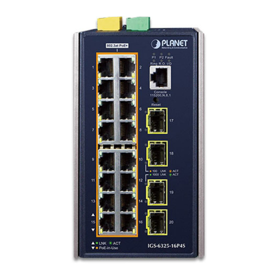
1. Package Contents Thank you for purchasing PLANET L3 Industrial Managed Switch, IGS-6325 DIN-rail series. The descriptions of these models are as follows: Industrial L3 16-Port 10/100/1000T 802.3at PoE + 4-Port IGS-6325-16P4S 100/1000X SFP Managed Ethernet Switch Industrial L3 8-Port 10/100/1000T + 4-Port 10G SFP+ IGS-6325-8T4X Managed Ethernet Switch Industrial L3 8-Port 10/100/1000T + 8-Port 100/1000X IGS-6325-8T8S SFP Managed Ethernet Switch Industrial L3 8-Port 10/100/1000T + 8-Port 100/1000X IGS-6325-8T8S4X SFP + 4-Port 10G SFP+ Managed Ethernet Switch Industrial L3 8-Port 10/100/1000T 802.3bt PoE + 2-Port IGS-6325-8UP2S 100/1000X SFP Managed Ethernet Switch Industrial L3 8-Port 10/100/1000T 802.3bt PoE + 2-Port IGS-6325-8UP2S2X 100/1000X SFP + 2-Port 10G SFP+ Managed Ethernet Switch “Industrial Managed Switch” mentioned in this Quick Installation Guide refers to the above models. -
Page 4: Requirements
2. Requirements The Industrial Managed Switch provides remote login interface for management purposes. The following equipment is necessary for further management: z Workstations running Windows XP/2003/Vista/7/8/2008/10, MAC OS X or later, Linux, UNIX, or other platforms are compatible with TCP/IP Protocols. z Workstations are installed with Ethernet NIC (Network Interface Card). z Serial Port Connection (Terminal) The above Workstations come with COM Port (DB9) or USB-to-RS232 converter. ... -
Page 5: Wiring The Power Inputs
3. Wiring the Power Inputs The Upper Panel of the Industrial Managed Switch indicates an inlet power socket and consists of one green terminal block connector within 6 contacts. Please follow the steps below to insert the power wire. 1. Insert positive/negative DC power wires into Contacts 1 and 2 for Power 1, or Contacts 5 and 6 for Power 2. - Page 6 Power 1 Power 2 Figure 3-4: The pin of 6-contact terminal block connector 1. The wire gauge for the terminal block should be in the range from 12 to 24 AWG. 2. Please check the wire AWG Ampere specification before Note connecting PLANET Industrial Managed Switch.
-
Page 7: Grounding The Device
3.1 Grounding the Device Users MUST complete grounding wired with the device; otherwise, a sudden lightning could cause fatal damage to the device. Earth Ground DI 0 DI 1 DO 0 DO 1 GND GND 1 2 3 4 5 6 1 2 3 4 5 6 1A@24V Input: 48-56V... -
Page 8: Terminal Setup
4. Terminal Setup To configure the system, connect a serial cable to a COM port on a PC or notebook computer and to RJ45 type serial (console) port of the Industrial Managed Switch. IGS Industrial Managed Switch PC/Workstation with Terminal Emulation Software RJ45 to DB9 RS232 Cable Serial Port Console Port... -
Page 9: Logging On To The Console
4.1 Logging on to the Console Once the terminal has been connected to the device, power on the Industrial Managed Switch and the terminal will display “running testing procedures”. The following console screen is based on the IGS-6325-16P4S. The display of the IGS-6325 series is the same as that of the IGS- 6325-16P4S. -
Page 10: Configuring Ip Address Via Console
4.2 Configuring IP Address via Console The Industrial Managed Switch is shipped with default IP address shown below: IP Address: 192.168.0.100 Subnet Mask: 255.255.255.0 To check the current IP address or modify a new IP address for the Switch, please use the procedure as follows: Display of the current IP Address 1. At the “#” prompt, enter “show ip interface brief”. -
Page 11: Storing Current Switch Configuration
The previous command would apply the following settings for the Industrial Managed Switch. IP Address: 192.168.1.100 Subnet Mask: 255.255.255.0 Figure 4-3: Configuring IP Address Screen 4. Repeat step 1 to check if the IP address has changed. 4.3 Storing current switch configuration 1. At the “#” prompt, enter the following command and press <Enter>. # copy running-config startup-config Figure 4-4: Saving Current Configuration Command Screen If the IP is successfully configured, the Industrial Managed Switch will apply the new IP address setting immediately. -
Page 12: Starting Web Management
5. Starting Web Management The following shows how to start up the Web Management of the Industrial Managed Switch. Note the Industrial Managed Switch is configured through an Ethernet connection. Please make sure the manager PC must be set to the same IP subnet address. - Page 13 3. After entering the password, the main screen appears as shown in Figure 5-3. Switch Menu Sub-menu Figure 5-3: Web Main Screen of Industrial Managed Switch The Switch Menu on the top of the Web page lets you access all the commands and statistics the Industrial Managed Switch provides. The Switch Menu always contains one or more buttons, such as “System”, “Switching”, “Routing”, “QoS”, “Security”, “PoE”, “Ring”, “ONVIF”...
-
Page 14: Saving Configuration Via Web
Figure 5-6: Switch Sub-menu Now, you can use the Web management interface to continue the Switch management. Please refer to the user manual for more. If you are not familiar with Switch functions or the related param- eter, press “Help icon” anytime on the Web page to get the help description. - Page 15 2. Press the “Save Configuration” button. 3. Or the other way to save the setting is to Click Maintenance, Save Startup Config.
-
Page 16: Recovering Back To Default Configuration
6. Recovering Back to Default Configuration IP address has been changed or admin password has been forgotten – To reset the IP address to the default IP address “192.168.0.100” and the user password to factory default mode (default password is admin), press the hardware-based reset button on the front panel for about 10 seconds. After the device is rebooted, you can log in the management Web interface within the same subnet of 192.168.0.xx and default password. - Page 17 Fault Ring R.O. 1000 LNK 10G LNK 1000 LNK 100 LNK 10/100/1000T 1000 10/100 LNK bt PoE-in-Use af/at PoE-in-Use PoE Usage 320W 240W 160W 802.3bt PoE++ Reset Button IGS-6325-8UP2S2X Reset Figure 6-3: IGS-6325-8UP2S/IGS-6325-8UP2S2X Reset Button...
-
Page 18: Customer Support
7. Customer Support Thank you for purchasing PLANET products. You can browse our online FAQ resource on PLANET web site first to check if it could solve your issue. If you need more support information, please contact PLANET switch support team. PLANET online FAQs: http://www.planet.com.tw/en/support/faq Switch support team mail address: support@planet.com.tw IGS-6325-DIN-rail Series User’s Manual: https://www.planet.com.tw/en/support/downloads?&method=keyword&keyword=I GS-6325&view=3#list (Please select your switch model name from the Product Model drop-down menu) Copyright © PLANET Technology Corp. 2019. Contents are subject to revision without prior notice.
Need help?
Do you have a question about the IGS-6325 DIN rail Series and is the answer not in the manual?
Questions and answers