Sign In
Upload
Download
Table of Contents
Contents
Add to my manuals
Delete from my manuals
Share
URL of this page:
HTML Link:
Bookmark this page
Add
Manual will be automatically added to "My Manuals"
Print this page
×
Bookmark added
×
Added to my manuals
Manuals
Brands
Planet Manuals
Network Router
IGS-801T
User manual
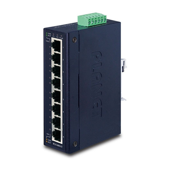
Planet IGS-801T User Manual
5/8-port 10/100/1000mbps industrial gigabit ethernet switch
Hide thumbs
Also See for IGS-801T
:
User manual
(20 pages)
1
2
3
Table Of Contents
4
5
6
7
8
9
10
11
12
13
14
15
16
17
18
19
20
21
22
23
24
page
of
24
Go
/
24
Contents
Table of Contents
Troubleshooting
Bookmarks
Table of Contents
Fcc Warning
Ce Mark Warning
Table of Contents
Introduction
Package Contents
How to Use this Manual
Product Features
Product Specifications
Installation
Product Description
Product Overview
Switch Front Panel
LED Indicators
Switch Upper Panel
Wiring the Power Inputs
Wiring the Fault Alarm Contact
Mounting Installation
DIN-Rail Mounting
Wall Mount Plate Mounting
Applicaiton
Switch Operation
Address Table
Learning
Forwarding & Filtering
Store-And-Forward
Auto-Negotiation
Troubleshooting
Appendix A: Networking Connection
Switch's RJ-45 Pin Assignments
Cable Pin Assignments
Advertisement
Quick Links
1
Led Indicators
2
Wiring the Power Inputs
3
Address Table
4
Troubleshooting
Download this manual
5/8-Port 10/100/1000Mbps
Industrial Gigabit Ethernet Switch
IGS-501 / IGS-801 / IGS-501T / IGS-801T
User's Manual
Table of
Contents
Previous
Page
Next
Page
1
2
3
4
5
Advertisement
Table of Contents
Need help?
Do you have a question about the IGS-801T and is the answer not in the manual?
Ask a question
Questions and answers
Related Manuals for Planet IGS-801T
Switch Planet IGS-501T User Manual
5-/8-port 10/100/1000mbps industrial gigabit ethernet switch (20 pages)
Network Router Planet IGS-501 User Manual
5/8-port 10/100/1000mbps industrial gigabit ethernet switch (24 pages)
Network Router Planet IGS-10020 Series User Manual
L2+ multi-port full gigabit managed ethernet switch (409 pages)
Network Router Planet IGS-20040MT User Manual
L2+ multi-port full gigabit managed ethernet switch (381 pages)
Network Router Planet IGS-5225-20T4C2X Quick Installation Manual
Industrial l2+ 20-port 10/100/1000t + 4-port tp/sfp combo + 2-port 10g sfp+ managed ethernet switch (-40~75 degrees c) (16 pages)
Network Router Planet IGS-5225-16T4S User Manual
Industrial l2+ gigabit ethernet managed switch igs-5225 series (391 pages)
Network Router Planet IGS-620TF User Manual
Industrial 4-port 10/100/1000base-t + 2-slot 100/1000base-x sfp ethernet switch (36 pages)
Network Router Planet IGS-604HPT-M12 User Manual
Industrial ip67-rated 4-port gigabit 802.3at poe + 2-port gigabit managed ethernet switch (389 pages)
Network Router Planet IGS-604HPT-M12 Quick Installation Manual
Industrial ip67-rated 4-port 10/100/1000t; 802.3at poe + 2-port 10/100/1000t m12 managed ethernet switch (-40~75 degrees c) (16 pages)
Network Router Planet IGS-5227-6T Quick Installation Manual
Industrual ip67-rated 6-port gigabit managed ethernet switch (24 pages)
Network Router Planet IGS-801M Quick Installation Manual
Industrial 8-port 10/100/1000mbps managed ethernet switch (2 pages)
Network Router Planet IGS-6325 DIN rail Series Quick Installation Manual
Industrial l3 multi-port gigabit managed ethernet switch (20 pages)
Network Router Planet IGS-4215-16T2S Quick Installation Manual
Industrial 16-port 10/100/1000t + 2-port 100/1000x sfp managed gigabit ethernet switch (16 pages)
Network Router Planet ISW-500T User Manual
Industrial 5-/8-port 10/100tx compact ethernet switch (16 pages)
Network Router Planet ISW-800T User Manual
Industrial 5-/8-port 10/100tx compact ethernet switch (16 pages)
Network Router Planet IVR-100 Series Quick Installation Manual
Industrial vpn security router (16 pages)
This manual is also suitable for:
Igs-801
Igs-501t
Igs-501
Table of Contents
Print
Rename the bookmark
Delete bookmark?
Delete from my manuals?
Login
Sign In
OR
Sign in with Facebook
Sign in with Google
Upload manual
Upload from disk
Upload from URL


Need help?
Do you have a question about the IGS-801T and is the answer not in the manual?
Questions and answers