Table of Contents
Advertisement
Quick Links
Advertisement
Table of Contents

Subscribe to Our Youtube Channel
Related Manuals for IFM DX1063


Summary of Contents for IFM DX1063
- Page 1 Operating instructions Universal display DX1063...
-
Page 2: Table Of Contents
DX1063 Universal display Contents Preliminary note ............. -
Page 3: Preliminary Note
Universal display DX1063 1 Preliminary note You will find instructions, technical data, approvals and further information using the QR code on the unit / packaging or at www.ifm.com. 1.1 Symbols used Requirement Instructions Reaction, result [...] Designation of keys, buttons or indications... -
Page 4: Safety Instructions
DX1063 Universal display 2 Safety instructions • The unit described is a subcomponent for integration into a system. – The system architect is responsible for the safety of the system. – The system architect undertakes to perform a risk assessment and to create documentation in accordance with legal and normative requirements to be provided to the operator and user of the system. -
Page 5: Intended Use
Universal display DX1063 3 Intended use The unit evaluates and displays sensor signals. The unit is intended for panel mounting. The fixing elements supplied are suited for a wall thickness up to 6 mm. -
Page 6: Function
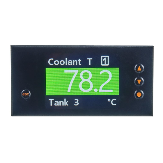
DX1063 Universal display 4 Function With the unit a wide variety of sensors can be operated and the corresponding physical values are displayed. If temperatures are to be measured via Pt100, Pt1000 or thermocouple, the temperature will be displayed in °C or °F (selectable). For measurement inputs such as current, voltage, frequency or counter, the scaling and indication can be freely selected in the display range from -1999 to 9999. -
Page 7: Installation
Universal display DX1063 5 Installation Fig. 1: installation 1: sealing 2: fixing element *Installation depth including connection terminal The fixing elements supplied are suited for a wall thickness up to 6 mm. u Make a panel cut-out (92 x 45 mm). u Remove the fixing elements from the unit. -
Page 8: Electrical Connection
DX1063 Universal display 6 Electrical connection The unit must be connected by a qualified electrician. u Observe the national and international regulations for the installation of electrical equipment. u Disconnect power. u Connect the unit as follows: 6.1 Wiring Fig. 2: Wiring 6.2 Connection examples 6.2.1 Voltage/Current... - Page 9 Universal display DX1063 AGND 0...1 V, 0...2 V AGND 0...1 V, 0...2 V Fig. 7: 3-wire sensor 0...1 V, 0...2 V Fig. 8: 3-wire sensor 0...1 V, 0...2 V with external voltage supply 0...10 V AGND 0...10 V AGND Fig. 9: 3-wire sensor 0...10 V Fig. 10: 3-wire sensor 0...10 V with external voltage supply...
-
Page 10: Temperature
DX1063 Universal display 0...10 V AGND 0...10 V AGND OUT+ OUT+ OUT- OUT- Fig. 15: 4-wire sensor 0...10 V Fig. 16: 4-wire sensor 0...10 V with external voltage supply 6.2.2 Temperature Pt100 Pt1000 Fig. 17: Pt100 3-wire Fig. 18: Pt1000 2-wire (connection of a 4-wire sensor possible by combining two... -
Page 11: Namur
Universal display DX1063 Fig. 22: Signal transmitter with PNP output Fig. 23: Signal transmitter with PNP output and with external voltage source Depending on the design of the system, an external resistance circuit can be helpful to reliably detect higher frequencies. 4,2 kΩ... -
Page 12: Counter
DX1063 Universal display NAMUR NAMUR NAMUR NAMUR Fig. 30: NAMUR sensor Fig. 31: NAMUR sensor with external voltage supply 6.2.5 Counter When used as a counter, use the connection examples for frequency/speed. The following figure shows the reset input connection. Reset Fig. 32: Manual reset with external pushbutton... -
Page 13: Operating And Display Elements
Universal display DX1063 7 Operating and display elements ▼ ▼ ● Fig. 33: Operating and display elements [▲] key [▼] key [●] key [esc] key display... -
Page 14: Menu
DX1063 Universal display 8 Menu Press the operating key [●] > 1 s to navigate from the process value display to the main menu and from there to the submenus. See also Parameter setting (Ò / 19). Process value display Main menu Input type... - Page 15 Universal display DX1063 Volt/Ampere 0...10 V 0...2 V 0...1 V 0...50 mV Input type Input range Main menu 0...20 mA 4...20 mA Sens V (0...10 V) Sens mA (0...20 mA) Volt/Ampere -1999…9999 End value Alarms -1999…9999 Start value General cccc ccc.c cc.cc c.ccc...
- Page 16 DX1063 Universal display Frequency PNP NAMUR Input type Input signal Main menu Frequency 9.999 Hz 99.99 Hz 999.9 Hz 9999 Hz Input range Filter 2 Hz 5 Hz 10 Hz 20 Hz 50 Hz 100 Hz 200 Hz 500 Hz No...
-
Page 17: Alarms Menu
Universal display DX1063 Count up / PNP NAMUR Input type Input signal Main menu Count down Counter Count base Pulses Seconds Minutes Positive Negative Alarms Active edge 0001…9999 Prescaler General Display 2 Hz 5 Hz 10 Hz 20 Hz 50 Hz 100 Hz 200 Hz 500 Hz No Filter -1999…9999... -
Page 18: General Menu
DX1063 Universal display 8.3 General menu General Input type Update time 0.1…2.0 s Main menu Input type 0.1…2.0 s Measuring time Average filter 01…20 Alarms None ADC Full range 5 % range 10 % range Overrange General -1999…9999 Min. display value Display Max. -
Page 19: Parameter Setting
Universal display DX1063 9 Parameter setting Parameters can be set before installation or during operation. If you change parameters during operation, this will influence the function of the plant. u Ensure that there will be no malfunctions in your plant. During parameter setting the unit remains in the operating mode. It continues to monitor with the existing parameter until the parameter setting has been completed. -
Page 20: Volt/Ampere
DX1063 Universal display 9.1.1 Volt/Ampere The unit displays the measured voltage or current value. In addition, it is possible to calibrate the unit via the connected measuring section. Carry out a calibration (optional): ü [Input type] [Volt/Ampere] is selected. u Select [Input range] and set the desired measuring range: •... - Page 21 Universal display DX1063 u Select [End value] and set the value displayed at the analogue input value [Analog end]. [Analog end] is the final value of the measuring range by default, but it can be adjusted. • -1999…9999 u Select [Start value] and set the value displayed at the analogue input value [Analog start]. This is the initial value of the measuring range by default, but it can be adjusted.
-
Page 22: Pt100(0)
DX1063 Universal display 9.1.2 Pt100(0) The unit displays the temperature value measured via a Pt100 or Pt1000 resistance thermometer. Parameter setting: ü [Input type] [Pt100(0)] is selected. u Select [Sensor type] and set the type/temperature range of the thermometer: Value Description Pt100 (200 °C) - Page 23 Universal display DX1063 Parameter setting: ü [Input type] [Frequency] is selected. u Select [Input signal] and set the type of input signal: • • • • NAMUR u Select [Input range] and set the frequency range: Value Description 9.999 Hz 0.000…9.999 Hz...
-
Page 24: Rpm/Speed
DX1063 Universal display displayed value End value Start value Frequency Frequency input frequency [Hz] start Fig. 46: Application [Frequency start] / [Frequency end] u Optionally select [Value offset] and set the value for the display offset: • -1999…9999 u Select [Linearization points] and set the desired number of linearization points: •... -
Page 25: Count Up / Count Down
Universal display DX1063 u Select [Number of cams] and set the number of pulses per revolution: • 0001…9999 u Select [Time base] and set the time base for the speed unit: • Second • Minute • Hour u Select [Decimal point] and set the position of the decimal point in the display: •... -
Page 26: Alarms
DX1063 Universal display • 2 Hz • 5 Hz • 10 Hz • 20 Hz • 50 Hz • 100 Hz • 200 Hz • 500 Hz • u Select [End value] and set the value to be displayed after reaching the final value of the measuring range: •... - Page 27 Universal display DX1063 Value Description Below limit The alarm is activated when the switch point is not reached. In window The alarm is activated in the specified window. Out of window The alarm is activated outside the specified window. Tab. 5: Ax mode...
-
Page 28: General Parameters / Safety Parameters - General
DX1063 Universal display This setting affects either the font colour or the background colour. This depends on [Ax alarm type]. u Select [Ax alarm type] and set whether the alarm is to be indicated via background colour or font colour: •... - Page 29 Universal display DX1063 Value Description None No indication of overflow or underflow. In these cases, the unit continues to display the highest / lowest value. [OL] is indicated if [Max. display value] is exceeded. [UL] is indicated if [Min. display value] is not reached.
- Page 30 DX1063 Universal display Value Description No function No function of this key in operating mode Taring In operating mode, press [▲] to perform taring (offset). Tab. 9: esc key The parameter [esc key] is only available with [Input type] [Volt/Ampere], [Frequency] and [RPM/Speed].
-
Page 31: Parameters For The Indication Of Measured Values - Display
Universal display DX1063 User level Can configure Serial number query ● ● ● ● ● ● ● [General] > [Serial number] Alarm thresholds ● ● ● ● ● ● — [Ax upper value], [Ax lower value] Alarm hysteresis ● ●... -
Page 32: Restore Factory Settings
DX1063 Universal display • White u Select [Signal name color] and set the font colour of the signal name in the event of an alarm: Value Description Default In the event of an alarm, the font colour of the signal name re- mains white. -
Page 33: Operation
Universal display DX1063 10 Operation After switching the supply voltage on, the unit displays the software version for 3 seconds. Then the unit switches into operating mode. Display indications correspond to the parameter setting. Alarms are visually reported in the display via a colour change of the background and font. A display overflow is displayed via [OL], a display underflow via [UL] (if configured). -
Page 34: Troubleshooting
DX1063 Universal display 11 Troubleshooting Error Cause Troubleshooting The unit permanently indicates overflow. The measured value at the input is too Check the measuring circuit. high. The display range of 9999 or the preset Check the supporting points, the select- measuring range was exceeded. -
Page 35: Maintenance, Repair And Disposal
Universal display DX1063 12 Maintenance, repair and disposal Cleaning the unit: u Disconnect the unit from the voltage supply. u Clean the unit from dirt using a soft, chemically untreated and dry micro-fibre cloth. The unit is maintenance-free. u After use, dispose of the unit in an environmentally friendly way in accordance with the applicable... -
Page 36: Factory Settings
DX1063 Universal display 13 Factory settings 13.1 Input type – Parameters for measuring signals Parameter Factory settings User settings Input type [Volt/Ampere] Input range 0…10 V • 0…10 V • 0…2 V • 0…1 V • 0...50 mV • 0...20 mA • 4...20 mA •... - Page 37 Universal display DX1063 Parameter Factory settings User settings Input type [Pt100(0)] Adjustment 00.0 °C -19.9…19.9 °C (00.0 °F) (-35.9…35.9 °F) Input type [Thermo] Sensor type Type K • Type L • Type J • Type K • Type B • Type S •...
- Page 38 DX1063 Universal display Parameter Factory settings User settings Input type [Frequency] Display P#5(Y) -1999…9999 Frequency P#5(X) 0 Hz 0000…9999 Hz Display P#6(Y) -1999…9999 Frequency P#6(X) 0 Hz 0000…9999 Hz Display P#7(Y) -1999…9999 Frequency P#7(X) 0 Hz 0000…9999 Hz Display P#8(Y) -1999…9999...
-
Page 39: Alarms - Parameters For Alarms A1
Universal display DX1063 Parameter Factory settings User settings Input type [Count up] / [Count End value 1000 -1999…9999 down] End count 1000 0001…9999 Reset 0000 0000…9999 Decimal point cccc • cccc • ccc.c • cc.cc • c.ccc Scale unit AAAAAAA…ZZZZZZZ 13.2 Alarms –... -
Page 40: Display - Parameters For The Indication Of Measured Values
DX1063 Universal display Parameter Factory settings User settings Overrange • None • ADC • Full range • 5 % range • 10 % range Min. display value -1999 -1999…9999 Max. display value 9999 -1999…9999 Direction keys No function • No function •...
Need help?
Do you have a question about the DX1063 and is the answer not in the manual?
Questions and answers