Table of Contents
Advertisement
Available languages
Available languages
Advertisement
Chapters
Table of Contents

Related Manuals for IFM Ecomat 200 DS2001


Summary of Contents for IFM Ecomat 200 DS2001
- Page 1 Betriebsanleitung Operating instructions Notice d'utilisation Monitor FS-1 / FS-1N Contrôleur FS-1 / FS-1N DS2001 DS2003 DS2004 DS2103 DS2104 MONITOR FS-1 N Frequency/Slip CH1CH2 CH3 CH4 RUNPRG TST KEY In 1 In 2 Out1 Out2...
-
Page 2: Table Of Contents
FS-1 / FS-1N MONITOR Die Betriebsanleitung ... gilt für alle Geräte des Typs Monitor FS-1 / FS-1N..richtet sich an fachkundige Personen im Sinne von EMV- und der Niederspan- nungs-Richtlinie..ist Bestandteil des Gerätes. Sie enthält Angaben zum korrekten Umgang mit dem Produkt. -
Page 3: Sicherheitshinweise
FS-1 / FS-1N MONITOR 1. Sicherheitshinweise Befolgen Sie die Angaben der Betriebsanleitung. Nichtbeachten der Hinweise, Ver- wendung außerhalb der nachstehend genannten bestimmungsgemäßen Verwen- dung, falsche Installation oder Handhabung können Beeinträchtigungen der Si- cherheit von Menschen und Anlagen zur Folge haben. Der Einbau und Anschluss muß... -
Page 4: Bestimmungsgemäße Verwendung
FS-1 / FS-1N MONITOR Das Gerät ist gemäß nachstehender technischer Spezifikation in einem weiten Um- gebungstemperaturbereich betreibbar. Aufgrund der zusätzlichen Eigenerwärmung kann es an den Bedienelementen und den Gehäusewandungen beim Berühren in heißer Umgebung zu hohen wahrnehmbaren Temperaturen kommen. Bei Fehlfunktion des Geräts oder bei Unklarheiten setzen Sie sich bitte mit dem Hersteller in Verbindung. - Page 5 FS-1 / FS-1N MONITOR Der Monitor ermittelt die prozentuale Abweichung zwischen den anliegenden Ein- gangsfrequenzen, vergleicht diese mit dem eingestellten Schaltpunkt [Schlupf in %] und schaltet Ausgang 1 gemäß der gewählten Schaltfunktion. – f Schlupf = x 100 [%] Zusammen mit dem integriertenen Drehzahlwächter für den Antrieb IN2 und dem Schaltausgang OUT2 ermöglicht der Monitor •...
-
Page 6: Bedien- Und Anzeigeelemente
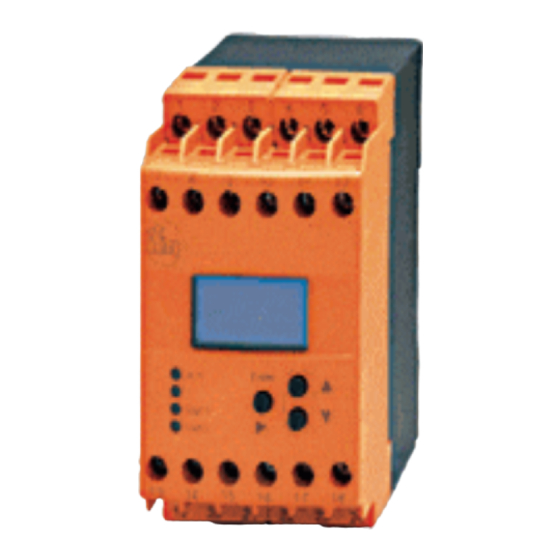
FS-1 / FS-1N MONITOR 3. Bedien- und Anzeigeelemente MONITOR FS-1 N Frequency/Slip In 1 Out1 In 2 Out2 Display (7/14-Segment) Indikatoren für Eingangskanäle und Betriebsmodi: CH1...CH4 Eingangskanäle (hier: CH1 und CH2) Run-Modus (Arbeitsbetrieb) Programmiermodus (Einstellen der Parameterwerte) Testfunktion (Offline-Überprüfung des Schaltverhaltens) Gerätestatus (Verriegelung) 1b Anzeige: Istwerte und Parameterwerte (5-stellig, numerisch) -
Page 7: Montage
FS-1 / FS-1N MONITOR 4. Montage Montieren Sie das Gerät auf eine DIN-Profilschiene oder mit Hilfe eines Monta- gesockels. Lassen Sie ausreichend Platz zu Boden oder Deckel des Schaltschrankes, um Luftzirkulation zu ermöglichen und übermäßige Erwärmung zu vermeiden. Beachten Sie beim Aneinanderreihen mehrerer Geräte die Eigenerwärmung aller Geräte. -
Page 8: Anschluss Der Sensoren (In1, 2)
6. E LEKTRISCHER NSCHLUSS Um die "limited voltage" Anforderungen gemäß UL 508 zu erfüllen, muss das Gerät aus einer galvanisch getrennten Quelle versorgt und durch eine Überstrom- schutzeinrichtung abgesichert werden. Soll der DC-Kreis geerdet werden (z.B. aufgrund nationaler Vorschriften), müssen die entsprechenden Richtlinien eingehalten werden (Schutzkleinspannung, Strom- kreis galvanisch getrennt von anderen Stromkreisen). -
Page 9: Lastkreise Relaisausgänge (Out1, 2)
FS-1 / FS-1N MONITOR d.h. es wird derselbe Zustand gemeldet, wie während der Anlaufüberbrückung. Die Überwachung startet nach Wegnehmen der Spannung und Ablauf der einge- stellten Anlaufüberbrückungszeit. Hinweis zum FS-1N: Die für die Reset-Eingänge benötigte 24V-Signalspannung steht nicht am FS-1N zur Verfügung. -
Page 10: Navigation Und Parameter-Übersicht
FS-1 / FS-1N MONITOR 6. Navigation und Parameter-Übersicht Die Navigation, Werteingabe und Bestätigung innerhalb der „spaltenförmig“ ange- legten Parameter erfolgt mit den / -Tasten und der -Taste. Die Parameter oberhalb von sind allgemeine Systemparameter. Entsprechend den zu überwachenden Maschinen oder Systemen werden sie nor- malerweise nur einmal bei der Inbetriebnahme eingestellt. -
Page 11: Systemparameter
FS-1 / FS-1N MONITOR Systemparameter Parameter Beschreibung, Werte, Voreinstellung Function Output (Schaltfunktion der Schaltausgänge 1/2) Relais zieht an (Transisitor leitend) bei Unterschreiten des Schaltpunktes SPx (= Zustandsmeldung OUT1 „Gleichlauf“; OUT2 „Antrieb Sollwert unterschritten“) Relais fällt ab (Transisitor gesperrt) bei Unterschreiten des Schaltpunktes SPx (= Fehlermeldung OUT2 „Antrieb Unterdrehzahl“;... - Page 12 FS-1 / FS-1N MONITOR Number of Cams (Anzahl Schaltnocken der Eingänge 1/2) Nockenanzahl, die pro Umdrehung registriert wird. Aus diesem Wert berechnet der Monitor die Drehzahl (gemessene Frequenz ÷ NCx = angezeigte Drehzahl in RPM). Bei Frequenzmessungen sollte NCx = 1 gesetzt bleiben. •...
-
Page 13: Applikationsparameter
FS-1 / FS-1N MONITOR Applikationsparameter Parameter Beschreibung, Werte, Voreinstellung Switch Point (Schaltpunkt für Schaltausgänge 1/2) Wert, bei dem der jeweilige Ausgang seinen Schaltzustand ändert. SP1 = Schaltpunkt Ausgang 1 (Schlupf-/Gleichlaufüberwachung) SP2 = Schaltpunkt Ausgang 2 (Drehzahlüberwachung Antrieb) Die Ausgänge schalten unabhängig voneinander. •... -
Page 14: Programmieren
FS-1 / FS-1N MONITOR 7. Programmierung Wird während des Betriebs eine Programmierung durchgeführt, können Sie mit berührungsgefährlichen Spannungen in Kontakt kommen. Stellen Sie da- her sicher, daß eine Elektrofachkraft die Programmierung übernimmt. Parameter-Änderungen während des Betriebs, insbesondere Änderungen der Schaltfunktion und der Schaltpunkte, können zu Fehlfunktionen in der Anlage führen. -
Page 15: Hinweise Zur Programmierung
FS-1 / FS-1N MONITOR Hinweise zur Programmierung RUN-Modus Auch während einer Programmierung verbleibt das Gerät intern im RUN-Modus! (Erkennbar am RUN-Indikator). D.h. bis zur Übernahme eines neuen Wertes mit der -Taste führt das Gerät seine Überwachungsfunktion auf Basis der vorher eingestellten Parameter aus und schal- tet Relais- und Transistorausgänge entsprechend. -
Page 16: Testmodus
FS-1 / FS-1N MONITOR 8. Testmodus Im Testmodus kann das Schaltverhalten des Monitors offline überprüft, eingestellt und gespeichert werden. Der Monitor durchläuft einen frei definierbaren Frequenz- bereich und schaltet die Ausgänge entsprechend der gewählten Schaltfunktion und der Schaltpunkte. Testmodus aktivieren/beenden Zum Aktivieren die Betriebsspannung anlegen und gleichzeitig die -Taste betäti- gen. -
Page 17: Technische Daten
FS-1 / FS-1N MONITOR 9. Technische Daten Spannungsversorgung Versorgungsspannung AC/DC-Eingang 110 ... 240 V AC/DC (50...60 Hz) Versorgungsspannung DC-Eingang 27 V DC (typ. 24 V DC) Spannungstoleranz -20 ... +10 % Leistungsaufnahme AC/DC-Eingang: 5 VA / DC-Eingang: 3 W Sensoreingänge FS-1 Sensortypen PNP/NPN;... -
Page 18: Maßzeichnung
FS-1 / FS-1N MONITOR Gerätedaten Gehäuse Klemmschienengehäuse; Kunststoff Abmessungen (H x B x T) 78 x 45 x 120 mm Gewicht 490 g Schutzart Gehäuse/Klemmen IP 50/20 Anschluss 21 Doppelkammerkastenklemmen; 2 x 2,5 mm² (AWG 14) Anzeige LC-Display; 7/14-Segment Umgebungsbedingungen Umgebungs-/ Lagertemperatur -20...+60°C / -25...+80°C Luftdruck... -
Page 19: Schaltbild Eingangsbeschaltung
FS-1 / FS-1N MONITOR Typische Eingangsbeschaltung FS-1 + sensor supply (24 V) ϑ 270E 10n0 270E - sensor supply SEITE... - Page 20 FS-1 / FS-1N MONITOR The operating instructions ... apply to all monitors type FS-1 / FS-1N..are for authorised persons according to the EMC and low voltage directives..are part of the unit. They contain information about the correct handling of the product.
-
Page 21: Safety Instructions
FS-1 / FS-1N MONITOR 1. Safety instructions Follow the operating instructions. Non-observance of the instructions, operation which is not in accordance with use as prescribed below, wrong installation or handling can affect the safety of people and the plant. The installation and connection must comply with the applicable national and in- ternational standards. -
Page 22: Function And Features
FS-1 / FS-1N MONITOR According to the technical specifications below the unit can be operated in a wide operating temperature range. Because of the additional internal heating the oper- ating elements and the housing walls can hive high perceptible temperatures when touched in hot environments. - Page 23 FS-1 / FS-1N MONITOR The monitor determines the deviation in percent between the input frequencies, compares it with the set switch point (slip in %) and switches output 1 according to the selected switching function. – f slip = x 100 [%] In conjunction with the integrated speed monitor for the drive IN2 and the switch- ing output OUT2 the monitor enables monitoring •...
-
Page 24: Operating And Indicating Elements
FS-1 / FS-1N MONITOR 3. Operating and indicating elements MONITOR FS-1 N Frequency/Slip In 1 Out1 In 2 Out2 1 Display (7/14-segment) 1a Indicators for input channels and operating modes: CH1...CH4 Input channels (here: CH1 and CH2) Run mode (normal operating mode) Programming mode (setting of the parameter values) Test function (offline check of the switching characteristics) Status of the unit (locking) -
Page 25: Mounting
FS-1 / FS-1N MONITOR 4. Mounting Mount the unit on a DIN rail or by means of a mounting base. Leave enough space between the unit and the top and bottom of the control cabinet to enable air circulation to avoid excessive heating. Take the internal heating of all units into account when mounting several units side by side. -
Page 26: Connection Of The Sensors (In1, 2)
FS-1 / FS-1N MONITOR The device shall be supplied from an isolating source and protected by an overcur- rent protection device such that the limited voltage circuit requirements in accor- dance with UL 508 are met. If the DC circuit is to be grounded (e.g. due to national regulations), the respective directives must be adhered to (safe extra-low voltage, circuit galvanically separated from other circuits). -
Page 27: Load Circuits Relay Outputs (Out1, 2)
FS-1 / FS-1N MONITOR Note on FS-1N: The 24 V voltage required for the reset inputs is not available to the FS-1N. It must be taken from an external voltage source. The reference point (GND) of the exter- nal power supply must be connected to terminal 1 of the monitor, otherwise no switching operation is possible. -
Page 28: Navigation And Parameter Table
FS-1 / FS-1N MONITOR 6. Navigation and parameter table The push buttons and the push button are used for the navigation, entry of values and acknowledgement within the parameters arranged in columns. The parameters above are general system parameters. They are normally set only once during commissioning depending on the machines or sys- tems to be monitored. -
Page 29: System Parameters
FS-1 / FS-1N MONITOR System parameters Parameters Description, values, default value Function Output (switching function of the switching outputs 1/2) Relay energises (transistor conductive) when the current value is below the switch point SPx (= signalled state OUT1 "synchronous movement"; OUT2 "drive below preset value") Relay de-energises (transistor blocked) when the current value is below the switch point SPx (= error message OUT2 "drive speed too low";... - Page 30 FS-1 / FS-1N MONITOR Number of Cams (on inputs 1/2) Number of cams detected per revolution. On the basis of this value the monitor calculates the rotational speed (measured frequency ÷ NCx = displayed speed in RPM). For frequency measurements NCx = 1 should remain set. •...
-
Page 31: Application Parameters
FS-1 / FS-1N MONITOR Application parameters Parameters Description, values, default value Switch Point (for switching outputs 1/2) Value at which the output changes its switching status. SP1 = switch point output 1 (slip/synchronous monitoring) SP2 = switch point output 2 (monitoring of the rotational speed of the drive) The outputs switch independent of each other. -
Page 32: Programming
FS-1 / FS-1N MONITOR 7. Programming If programming takes place during operation, dangerous contact voltage can occur. Therefore ensure that programming is done by a qualified electrician. Parameter changes during operation, specially changes of the switching function and the switch points can lead to malfunction in the plant. There- fore disconnect it during the change and then check the function. -
Page 33: Notes On Programming
FS-1 / FS-1N MONITOR Notes on programming RUN mode During programming the unit internally remains in the RUN mode! (RUN indicator visible). This means that until a new value is acknowledged with the push button unit carries out its monitoring function on the basis of the previously set parame- ters and switches the relay and transistor outputs accordingly. -
Page 34: Test Mode
FS-1 / FS-1N MONITOR 8. Test mode In the test mode the switching behaviour of the monitor can be checked, set and stored offline. The monitor runs through a freely definable frequency range and switches the outputs according to the selected switching function and switch points. -
Page 35: Technical Data
FS-1 / FS-1N MONITOR 9. Technical data Voltage supply Supply voltage AC/DC input 110 ... 240 V AC/DC (50...60 Hz) Supply voltage DC input 27 V DC (typ. 24 V DC) Voltage tolerance -20 ... +10 % Power consumption AC/DC input: 5 VA / DC input: 3 W Sensor inputs FS-1 Sensor types PNP/NPN;... -
Page 36: Scale Drawing
FS-1 / FS-1N MONITOR Unit data Housing for rail mounting, plastic Dimensions (H x W x D) 78 x 45 x 120 mm Weight 490 g Protection rating housing/terminals IP 50/20 Connection 21 dual-chamber terminals, 2 x 2.5 mm² (AWG 14) Indication LCD display, 7/14-segment Environmental conditions... -
Page 37: Input Circuit Diagram
FS-1 / FS-1N MONITOR Typical input circuit FS-1 + sensor supply (24 V) ϑ 270E 10n0 270E - sensor supply PAGE... - Page 38 FS-1 / FS-1N CONTRÔLEUR La notice d'utilisation ... s'applique à tous les contrôleurs FS-1 / FS-1N..s'adresse à des personnes compétentes selon les directives CEM et basse ten- sion..fait partie de l'appareil. Elle fournit des indications sur l'utilisation correcte du produit.
- Page 39 FS-1 / FS-1N CONTRÔLEUR 1. Remarques sur la sécurité Respectez les indications de la notice d'emploi. Le non-respect des remarques, l'emploi non conforme aux prescriptions, le montage ou les manipulations incor- rects peuvent porter atteinte à la sécurité des personnes et des installations. Le montage et le raccordement doivent être conformes aux normes nationales et internationales en vigueur.
-
Page 40: Fonctionnement Et Caractéristiques
FS-1 / FS-1N CONTRÔLEUR L'appareil peut être employé dans une grande plage de températures ambiantes selon la spécification technique ci-dessous. En raison de l'échauffement interne supplémentaire, de hautes températures sensibles peuvent se produire sur les élé- ments de service et les parois du boîtier lors du contact en ambiance chaude. En cas de mauvais fonctionnement de l'appareil ou en cas de doute prenez contact avec le fabricant. - Page 41 FS-1 / FS-1N CONTRÔLEUR Le contrôleur détermine la déviation en pour cent entre les fréquences d'entrée, la compare avec le point de commutation réglé (glissement en %) et commute la sortie 1 selon la fonction de commutation choisie. – f glissement = x 100 [%] En combinaison avec le contrôle de glissement/synchronisme, le contrôleur permet...
-
Page 42: Eléments De Service Et D'indication
FS-1 / FS-1N CONTRÔLEUR 4. Eléments de service et d'indication MONITOR FS-1N Frequency/Slip In 1 Out1 In 2 Out2 1 Afficheur (segments 7/14) 1a Indicateurs pour des voies d'entrée et modes de fonctionnement: CH1...CH4 Voies d'entrée (ici: CH1 et CH2) Mode Run (mode de fonctionnement normal) Mode de programmation (réglage des valeurs de paramètre) Fonction de test (Contrôle "offline"... -
Page 43: Montage
FS-1 / FS-1N CONTRÔLEUR 5. Montage Monter l'appareil sur un rail DIN ou à l'aide d'une embase de montage. Laisser suf- fisamment d'espace vers le bas ou le haut de l'armoire électrique permettant ainsi une libre circulation de l'air pour éviter un échauffement excessif. Lorsque plusieurs appareils sont montés côte à... -
Page 44: Raccordement Des Capteurs (In1, 2)
FS-1 / FS-1N CONTRÔLEUR Afin de répondre aux exigences de la norme "UL 508" pour la catégorie "limited voltage", l'appareil doit être impérativement alimenté par une alimentation isolée galvaniquement et équipé d'un dispositif de protection contre les courants de sur- charge. -
Page 45: Circuits De Charge Sorties De Relais (Out1, 2)
FS-1 / FS-1N CONTRÔLEUR re le même état que pendant la temporisation de démarrage est signalé. Si la ten- sion n'est plus appliquée et que la temporisation de démarrage réglée est écoulée, la fonction de surveillance est activée. Remarque sur FS-1N: La tension 24 V nécessaire pour les entrées reset n'est pas disponible sur le FS-1N. -
Page 46: Topographie Navigation/Paramètres
FS-1 / FS-1N CONTRÔLEUR 7. Topographie navigation/paramètres Les boutons et le bouton sont utilisés pour la navigation, la saisie de va- leurs et la validation des paramètres indiqués sous forme de colonnes. Les paramètres au-dessus de sont des paramètres de système généraux. -
Page 47: Paramètres De Système
FS-1 / FS-1N CONTRÔLEUR Paramètres de système Paramètre Description, valeurs, valeur par défaut Function Output (fonction de commutation des sorties de commutation 1 et 2) Relais s'enclenche (transistor à l'état passant) lorsque la vitesse de rotation est inférieure au seuil de commutation SPx (= signal d'état OUT1 "synchronisme";... - Page 48 FS-1 / FS-1N CONTRÔLEUR Number of Cams (nombre des cames sur les entrées 1/2) Nombre de cames enregistré par tour. A partir de cette valeur le contrôleur calcule la vitesse de rotation (fréquence mesurée ÷ NCx = vitesse de rotation affichée en RPM ). En cas de mesures de fréquence NCx doit rester = 1.
-
Page 49: Paramètres D'application
FS-1 / FS-1N CONTRÔLEUR Paramètres d'application Paramètres Description, valeurs, valeur par défaut Switch Point (seuil de commutation sorties de commutation 1/2) Valeur à laquelle la sortie respective change son état de commutation. SP1 = point de commutation sortie 1 (surveillance glissement/synchronisme) SP2 = point de commutation sortie 2 (surveillance vitesse de rotation d'entraînement) Les sorties commutent indépendamment l'une de l'autre. -
Page 50: Programmation
FS-1 / FS-1N CONTRÔLEUR 8. Programmation Si la programmation est effectuée pendant le fonctionnement, des tensions dangereuses au contact peuvent se produire. S'assurer qu'un électricien qua- lifié effectue la programmation. Une modification des paramètres pendant le fonctionnement, notamment une modification de la fonction de commutation et des seuils de commuta- tion peuvent mener à... -
Page 51: Remarques Sur La Programmation
FS-1 / FS-1N CONTRÔLEUR Remarques sur la programmation Mode RUN Pendant la programmation l'appareil reste en interne au mode RUN! (Indicateur RUN visible). C'est-à-dire que jusqu'à la validation d'une nouvelle valeur par le bouton l'ap- pareil exécute sa fonction de surveillance à la base des paramètres réglés aupara- vant et commute les sorties de relais et transistor. -
Page 52: Mode De Test
FS-1 / FS-1N CONTRÔLEUR 8. Mode de test En mode de test le comportement de commutation du contrôleur peut être vérifié, réglé et mémorisé offline. Le contrôleur passe par une plage de fréquence à définir au libre choix et commute les sorties selon la fonction de commutation sélec- tionnée et les seuils de commutation. -
Page 53: Données Techniques
FS-1 / FS-1N CONTRÔLEUR 9. Données techniques Alimentation en tension Tension d'alimentation entrée AC/DC 110 ... 240 V AC/DC (50...60 Hz) Tension d'alimentation entrée DC 27 V DC (typ. 24 V DC) Tolérance de tension -20 ... +10 % Consommation de puissance entrée AC/DC: 5 VA / entrée DC: 3 W Entrées capteurs FS-1 Types capteurs... -
Page 54: Schéma D'encombrement
FS-1 / FS-1N CONTRÔLEUR Données appareil Boîtier montage sur rail, plastique Dimensions (H x L x P) 78 x 45 x 120 mm Poids 490 g Protection boîtier/bornes IP 50/20 Raccordement 21 bornes à chambres jumelées; 2 x 2,5 mm² (AWG 14) Indication afficheur LCD, (segments 7/14) Conditions environnantes... -
Page 55: Schéma Technologie Entrée
FS-1 / FS-1N CONTRÔLEUR Technologie entrée typique FS-1 + sensor supply (24 V) ϑ 270E 10n0 270E - sensor supply PAGE...
Need help?
Do you have a question about the Ecomat 200 DS2001 and is the answer not in the manual?
Questions and answers