Table of Contents
Advertisement
Quick Links
Advertisement
Table of Contents

Related Manuals for IFM SL5105


Summary of Contents for IFM SL5105
- Page 1 Operating instructions Airflow monitor SL5105...
-
Page 2: Table Of Contents
SL5105 Airflow monitor Contents Preliminary note ............. -
Page 3: Preliminary Note
Airflow monitor SL5105 1 Preliminary note You will find instructions, technical data, approvals and further information using the QR code on the unit / packaging or at www.ifm.com. 1.1 Symbols used Requirement Instructions Reaction, result [...] Designation of keys, buttons or indications... -
Page 4: Safety Instructions
SL5105 Airflow monitor 2 Safety instructions • The unit described is a subcomponent for integration into a system. – The system architect is responsible for the safety of the system. – The system architect undertakes to perform a risk assessment and to create documentation in accordance with legal and normative requirements to be provided to the operator and user of the system. -
Page 5: Intended Use
Airflow monitor SL5105 3 Intended use The unit monitors airflows and switches a relay. -
Page 6: Function
• Normally open: relay energises. green • Normally closed: relay de-energises. below the set value • Normally open: relay de-energises. • Normally closed: relay energises. *Information on the unit type (NO or NC) Ò Technical data at http://documentation.ifm.com. -
Page 7: Installation
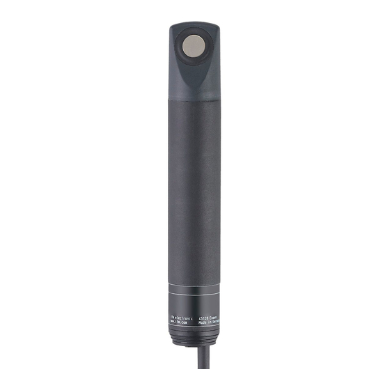
Airflow monitor SL5105 5 Installation u Drill a hole with a diameter of 24 mm in the pipe. u Mount the unit using the supplied mounting clamp: • Use the supplied seal for a hermetically sealed installation. • The sensor head must protrude completely into the airflow and should be in the area of the highest flow velocity. -
Page 8: Electrical Connection
SL5105 Airflow monitor 6 Electrical connection The unit must be connected by a qualified electrician. Observe the national and international regulations for the installation of electrical equipment. Voltage supply according to SELV, PELV. The design of the unit complies with protection class II. -
Page 9: Settings
Airflow monitor SL5105 7 Settings LEDs setting potentiometer sensitivity Fig. 5: Operating and display elements Flow adjustment for setting the switching point: u Switch on the power supply. u Let the normal flow circulate in the installation and keep it constant. u Continue with step 1 or 2.
Need help?
Do you have a question about the SL5105 and is the answer not in the manual?
Questions and answers