Table of Contents
Advertisement
Quick Links
Advertisement
Table of Contents

Related Manuals for IFM DP2200


Summary of Contents for IFM DP2200
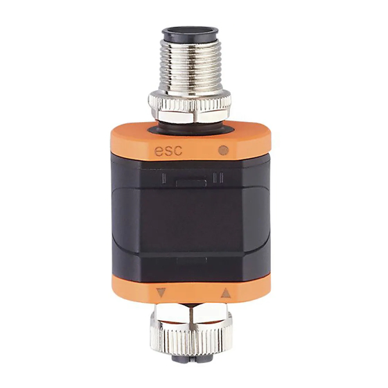
- Page 1 Operating instructions Analogue threshold display DP2200...
-
Page 2: Table Of Contents
DP2200 Analogue threshold display Contents Preliminary note ............. - Page 3 Analogue threshold display DP2200 10.2 Functions output 2 ............23 11 Troubleshooting .
-
Page 4: Preliminary Note
DP2200 Analogue threshold display 1 Preliminary note You will find instructions, technical data, approvals and further information using the QR code on the unit / packaging or at www.ifm.com. 1.1 Symbols used Requirement Instructions Reaction, result [...] Designation of keys, buttons or indications... -
Page 5: Safety Instructions
Analogue threshold display DP2200 2 Safety instructions • The unit described is a subcomponent for integration into a system. – The system architect is responsible for the safety of the system. – The system architect undertakes to perform a risk assessment and to create documentation in accordance with legal and normative requirements to be provided to the operator and user of the system. -
Page 6: Intended Use
The unit is not suited for environments with particular requirements on mechanical stability (e.g. shock/vibration). The unit is intended for indoor use only. u Observe the operating conditions (Ò Technical data at www.ifm.com). 3.1 Block diagram DP2200 OUT1 (SIO / IO-Link) -
Page 7: Function
Analogue threshold display DP2200 4 Function There are basically two modes in which the device can be operated: • As stand-alone device The device compares the measured current value with the set parameters and switches its output according to the selected parameters. This mode is without IO-Link functionality. The parameters can, however, also be set with an IO-Link tool. -
Page 8: Application Example
DP2200 Analogue threshold display 4.2.2 Application example 4...20 mA Fieldbus 4...20 mA 24 V DC Fig. 3: Application example with IO-Link master Analogue sensor (e.g. pressure sensor) Threshold display Fully bidirectional IO-Link communication Looping through an analogue input signal • Remote display: reading and displaying the measured current •... -
Page 9: Installation
Analogue threshold display DP2200 5 Installation u Install the device so that the M12 connection parts and the device are protected from mechanical stress such as shock and vibration. u If necessary, fix the device with a mounting clip. Use M4 screw or cable tie for this purpose. -
Page 10: Electrical Connection
DP2200 Analogue threshold display 6 Electrical connection The unit must be connected by a qualified electrician. Observe the national and international regulations for the installation of electrical equipment. Voltage supply according to SELV, PELV. The circuit is insulated from device surfaces that could be touched with basic insulation according to IEC 61010-1 (secondary circuit with max. -
Page 11: Removing The Connector With Vibration Protection
Analogue threshold display DP2200 u Tighten the cable plug using 1.8 ± 0.1 Nm. u Provide all outgoing cables with suitable strain relief after a maximum of 200 mm. Observe the minimum bending radius of the cables (Ò information from the cable manufacturer). -
Page 12: Operating And Display Elements
DP2200 Analogue threshold display 7 Operating and display elements 7.1 Push rings (pushbuttons) To execute an [esc], [●], [▼] or [▲] command, press the corresponding corner of a push ring. Button Function [esc] Escape Return to the previous menu. Exit parameter setting without saving the new value. -
Page 13: Representation Of The Measured Current Value
Analogue threshold display DP2200 Error signals and diagnosis: Troubleshooting In the operating mode the input current value is displayed. The scaling depends on the parameter ScAL ─ scaling of the displayed value (Ò / 17). 7.3.1 Representation of the measured current value 20.5... -
Page 14: Menu
DP2200 Analogue threshold display 8 Menu 8.1 General Irrespective of the operating mode (standard IO mode or IO-Link device) there are two options to set the parameters of the unit: • directly on the device via the menu (Ò Parameter setting) •... -
Page 15: Menu Structure
Analogue threshold display DP2200 8.2 Menu structure 4.10...20.00 4.10...20.00 1234 4.00...19.90 4.00...19.90 A.trm Hno Hnc Fno 0.0...50.0 0.0...50.0 ScAL OFF cccc ccc.c cc.cc c.ccc C.ASP -746...9745 C.AEP -366...9366 coLr rEd GrEn r1ou G1ou r-cF G-cF 4.10...20.00 4.00...19.90 0.000...4.000 Operating mode: Operation (Ò / 23) Main menu: Parameters of the main menu (Ò / 15) -
Page 16: Fh1/Fl1 ─ Min/Max Switching Limits For Window Function
DP2200 Analogue threshold display [rP1] follows the changes of [SP1] and keeps the set hysteresis. 8.3.2 FH1/FL1 ─ min/max switching limits for window function Upper/lower limit for measuring current at which OUT1 switches within the window setting. The parameters are only displayed if the window function [Fno] or [Fnc] is set in [ou1]. -
Page 17: Ds1/Dr1 ─ Switching Delay/Switch-Off Delay For Out1
Analogue threshold display DP2200 • [Hnc] = hysteresis function / normally closed • [Fno] = window function / normally open • [Fnc] = window function / normally closed See also: SP1/rP1 ─ set point/reset point OUT1 (Ò / 15) FH1/FL1 ─ min/max switching limits for window function (Ò / 16) 8.4.4 dS1/dr1 ─... -
Page 18: Colr ─ Display Colours And Colour Changes
DP2200 Analogue threshold display Menu setting example 100.0 ScAL ccc.c C.ASP C.AEP 100.0 Input 10 mA Display 37.5 [mA] Fig. 9: Example with scaled display value 8.4.7 coLr ─ display colours and colour changes Assignment of the display colours "red" and "green" within the measuring range. -
Page 19: Dis ─ Refresh Rate Of The Displayed Measured Value
Analogue threshold display DP2200 4 mA 20 mA 4 mA 20 mA Fig. 14: Function [r-cF] Fig. 15: Function [G-cF] For b/w printouts: gn = green, rd = red 8.4.9 diS ─ refresh rate of the displayed measured value • [OFF][ = The measured value display is deactivated in the operating mode.] •... -
Page 20: S.loc - Software Locking
DP2200 Analogue threshold display 8.5.2 S.Loc – software locking Value: ON/OFF With ON, the device is locked for local menu settings. Unlocking only via IO-Link. 8.5.3 Application-specific tag Customer-specific application description, max. 32 characters long. Default value: “ *** ” / can be freely defined by the customer... -
Page 21: Parameter Setting
Analogue threshold display DP2200 9 Parameter setting During parameter setting the unit remains in the operating mode. It continues its monitoring functions with the existing parameters until the parameter setting has been completed. 9.1 Parameter setting in general Each parameter setting consists of 6 steps:... -
Page 22: Notes On Programming
DP2200 Analogue threshold display Step Display u Press [esc]. u Press - [▼] or [▲] several times until the current measured value is displayed. - or wait for the timeout function (approx. 30 s). w The unit has returned to the operating mode. -
Page 23: Operation
Analogue threshold display DP2200 10 Operation After power on, the device is in the operating mode (SIO). It carries out its measurement and evaluation functions and provides output signals according to the set parameters (Ò Menu). 10.1 Functions output 1 OUT1 (connector, pin 4): •... -
Page 24: Troubleshooting
DP2200 Analogue threshold display 11 Troubleshooting Display Error Troubleshooting Power Supply voltage too low. Check/correct the supply voltage: Electrical connection (Ò / 10) flashes Excessive current at switching out- Check switching output OUT1 for put OUT1. short circuit or excessive current. Remove the fault. -
Page 25: Maintenance, Repair And Disposal
Analogue threshold display DP2200 12 Maintenance, repair and disposal The operation of the unit is maintenance-free. Only the manufacturer is allowed to repair the unit. u After use dispose of the device in an environmentally friendly way in accordance with the applicable national regulations. -
Page 26: Factory Settings
DP2200 Analogue threshold display 13 Factory settings Parameter Factory settings User settings SP1/FH1 Set point OUT1 6.00 rP1/FL1 Reset point OUT1 5.00 A.Trm Analogue termination OUT2 • OFF • On Output function OUT1 • Hno • Hnc • Fno • Fnc Switching delay OUT1 0.0 s...
Need help?
Do you have a question about the DP2200 and is the answer not in the manual?
Questions and answers