Table of Contents
Advertisement
Quick Links
Advertisement
Table of Contents

Related Manuals for IFM DP2122


Summary of Contents for IFM DP2122
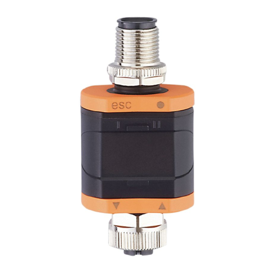
- Page 1 Operating instructions Speed monitor DP2122...
-
Page 2: Table Of Contents
DP2122 Speed monitor Contents Preliminary note ............. . - Page 3 Speed monitor DP2122 8.6.7 coLr ─ display colours and colour changes ....... . . 23 8.6.8...
-
Page 4: Preliminary Note
DP2122 Speed monitor 1 Preliminary note You will find instructions, technical data, approvals and further information using the QR code on the unit / packaging or at www.ifm.com. 1.1 Symbols used Requirement Instructions Reaction, result [...] Designation of keys, buttons or indications... -
Page 5: Safety Instructions
Speed monitor DP2122 2 Safety instructions • The unit described is a subcomponent for integration into a system. – The system architect is responsible for the safety of the system. – The system architect undertakes to perform a risk assessment and to create documentation in accordance with legal and normative requirements to be provided to the operator and user of the system. -
Page 6: Intended Use
Signals depending on the selected switching function The unit is not suited for environments with particular requirements on mechanical stability (e.g. shock/vibration). The unit is intended for indoor use only. u Observe the operating conditions (Ò Technical data at www.ifm.com). -
Page 7: Function
Description Displays the frequency in Hz Application Standard applications with frequency measurement in Hz IODD designation DP2122 Factory setting / (CMPT=HZ_M) IO-Link device ID 1167 d / 00 04 8f h IO-Link parameter CMPT HZ_M (default) Operating mode 2: rpnM... -
Page 8: Application Example
DP2122 Speed monitor 4.2.2 Application example Fieldbus Fig. 2: Application example with IO-Link master Conveyor belt and pulse pick-up DP2122 Fully bidirectional IO-Link communication IO-Link master - Remote parameter setting: reading and changing the pa- rameter setting. Fieldbus (e.g. Profibus, Profinet etc.) 4.2.3 IO Device Description (IODD) -
Page 9: Function Diagrams
Speed monitor DP2122 4.4 Function diagrams 4.4.1 Single point mode SP1: Overspeed: Reset point / underspeed: Switch point SP1+H: Overspeed: Switch point / underspeed: Reset point SP1+H Fig. 4: NO (IO-Link parameter LoGc: no / high active) If a set rotational speed is not reached, this is signalled by the switching signal as open. -
Page 10: Two Point Mode
DP2122 Speed monitor SP1: switch-off point window SP1+H: Switch-on point SP2: switch-off point window SP2-H SP1+H SP2-H: Switch-on point Fig. 7: NC (IO-Link parameter LoGc: nc / low active) If the set speed range is left, the swicthing signal will signal this as closed. -
Page 11: Deactivated Mode
Speed monitor DP2122 If a set rotational speed is not reached, this is signalled by the switching signal as closed. 4.4.4 Deactivated mode NO (IO-Link parameter LoGc: no / high active) The switching signal is always signalled as open. NC (IO-Link parameter LoGc: nc / low active) The switching signal is always signalled as closed. -
Page 12: Switch-Off Delay
DP2122 Speed monitor 4.4.7 Switch-off delay The switch-off delay enables filtering of input signals. The switching delay is activated or restarted by a negative switching edge of the input signal. Only if the input signal is still inactive after the delay time has elapsed, the output wil be set to the inactive switching state. -
Page 13: Installation
Speed monitor DP2122 5 Installation u Install the unit so that the M12 connection parts and the unit are protected from mechanical stress such as shock and vibration. u If necessary, fix the unit with a clamp (use M4 screw or cable tie). -
Page 14: Electrical Connection
DP2122 Speed monitor 6 Electrical connection The device must be connected by a qualified electrician. Observe the national and international regulations for the installation of electrical equipment. Voltage supply according to EN 50178, SELV, PELV. CAUTION Input current is not limited. w No fire protection. -
Page 15: Mounting The Connector
Speed monitor DP2122 6.1 Mounting the connector To achieve the protection rating indicated in the data sheet, the following has to be observed: u Use IO-Link cable with IP class. u Use M12 connectors with gold-plated contacts. u Connect the connector with the unit. The arrow indicates the position of the coding. -
Page 16: Operating And Display Elements
DP2122 Speed monitor 7 Operating and display elements 1: Push rings (pushbuttons) Here, the Enter button [●] is shown pressed, as an example. 2: LEDs 3: Display 7.1 Push rings (pushbuttons) To execute an [esc], [●], [▼] or [▲] command, press the corresponding corner of a push ring. -
Page 17: Display
Speed monitor DP2122 7.3 Display Colour Designation Red/green 7-segment LED display, 4 digits, with colour change Error signals and diagnosis: Troubleshooting When [▼] or [▲] is pressed during the operating mode for 1 second, the unit of measurement will be displayed. The displayed unit of measurement depends on the parameter C.uni. -
Page 18: Menu
DP2122 Speed monitor 8 Menu If a scaling is set, the menu settings of all frequency and speed dependent parameters (SP, cFH, etc.) are also scaled. 8.1 General Irrespective of the operating mode (standard IO mode or IO-Link device) there are two options to set the parameters of the unit: •... -
Page 19: Menu Structure
Speed monitor DP2122 8.2 Menu structure 8.2.1 Operating mode 1 SSC1 ModE 2-P OFF 1234 LoGc 0.2...2000 0.1...1999 0.5...100 0...99.99 0...99.99 PnP nPn SSC2 ModE 2-P OFF LoGc 0.2...2000 0.1...1999 0.5...100 0...99.99 0...99.99 0...999.9 ScAL OFF cccc ccc.c cc.cc c.ccc C.FEP 500...4000 C.uni... -
Page 20: Operating Mode 2
DP2122 Speed monitor 8.2.2 Operating mode 2 SSC1 ModE 2-P OFF 1234 LoGc 0.002...120.0 krPM 0.001...119.9 0.5...100 0...99.99 0...99.99 PnP nPn SSC2 ModE 2-P OFF LoGc 0.002...120.0 0.001...119.9 0.5...100 0...99.99 0...99.99 0...999.9 PrSC 1...99 coLr rEd GrEn r1ou G1ou r-cF G-cF 0.002...120.0... -
Page 21: Ssc2 ─ Speed Monitor Out2
Speed monitor DP2122 8.3.2 SSC2 ─ speed monitor OUT2 The parameter opens the menu of the settings for OUT2 of the speed monitor. 8.3.3 EF ─ extended functions The parameter opens the extended functions menu. 8.4 Parameters for OUT1 (SSC1) 8.4.1 ModE ─ switch point mode Setting of the switch point mode. -
Page 22: Ds ─ Switching Delay
DP2122 Speed monitor 8.4.6 dS ─ switching delay Delay when the output changes to the active switching status. Setting range: 0...99.99 s Resolution 0.01 s 8.4.7 dr ─ switch-off delay Delay when the output changes to the idle state. Setting range: 0...99.99 s Resolution 0.01 s... -
Page 23: C.fep ─ Custom User Endpoint For Frequency
Speed monitor DP2122 • [OFF] = indication in Hz with automatic decimal point setting. • [cccc] = indication without decimal place. • [ccc.c] = indication with 1 decimal place. • [cc.cc] = indication with 2 decimal places. • [c.ccc] = indication with 3 decimal places. -
Page 24: Cfh/Cfl ─ Upper/Lower Value For Colour Change
DP2122 Speed monitor OUT1 OUT1 0 Hz 2000 Hz 0 Hz 2000 Hz 0 rpm 120000 rpm 0 rpm 120000 rpm Fig. 13: Hysteresis function with [r1ou] Fig. 14: Hysteresis function with [G1ou] For b/w printouts: gn = green, rd = red •... -
Page 25: Dis.u ─ Refresh Rate Of The Displayed Measured Value
Speed monitor DP2122 • [On] = the measured value display is switched on in the operating mode. Press any button to activate the display for at least 30 s in the switched-off state. 8.6.10 diS.U ─ refresh rate of the displayed measured value •... -
Page 26: Application-Specific Tag
DP2122 Speed monitor 8.7.7 Application-specific tag Customer-specific application description, max. 32 characters long. Default value: “ *** ” / can be freely defined by the customer 8.7.8 Location tag Customer-specific location tag of the unit, max. 32 characters long. Default value: “ *** ” / can be freely defined by the customer 8.7.9 Function tag... -
Page 27: Parameter Setting
Speed monitor DP2122 9 Parameter setting During parameter setting the unit remains in the operating mode. It continues its monitoring functions with the existing parameters until the parameter setting has been completed. 9.1 Parameter setting in general Each parameter setting consists of 6 steps:... -
Page 28: Notes On Programming
DP2122 Speed monitor 9.2 Notes on programming 9.2.1 Locking / unlocking The unit can be locked electronically to prevent unauthorised setting. Set parameter values and settings can be displayed but not changed. To lock the unit: u Make sure that the unit is in normal operating mode. -
Page 29: Operation
Speed monitor DP2122 10 Operation After power on, the unit is in the operating mode (SIO). It carries out its measurement and evaluation functions and provides output signals according to the set parameters: Menu. -
Page 30: Troubleshooting
DP2122 Speed monitor 11 Troubleshooting Display, Error Troubleshooting Power Supply voltage too low. Check/correct the supply voltage: Electrical connection (Ò / 14) flashes flashes Excessive current at the switching Check switching output for short output OUTx (see LED I/II). circuit or excessive current. Re- move the fault. -
Page 31: Maintenance, Repair And Disposal
Speed monitor DP2122 12 Maintenance, repair and disposal Cleaning the unit: u Disconnect the unit from the voltage supply. u Clean the unit from dirt using a soft, chemically untreated and dry micro-fibre cloth. The operation of the unit is maintenance-free. -
Page 32: Factory Settings
DP2122 Speed monitor 13 Factory settings Parameters Factory settings User settings SSC1.ModE Switch point mode OUT1 • 1-P • and • 2-P • OFF SSC1.LoGc Switch point logic OUT1 • no • nc SSC1.SP1 Switch point 1 OUT 1 SSC1.SP2 Switch point 2 OUT 1 SSC1.HyS... - Page 33 Speed monitor DP2122 Parameters Factory settings User settings diS.b Display power on • On • OFF diS.U Refresh rate of the displayed d2 (200 ms) • OFF value • d1 (50 ms) • d2 (200 ms) • d3 (600 ms)
Need help?
Do you have a question about the DP2122 and is the answer not in the manual?
Questions and answers