
Related Manuals for IFM Efector 300 VS2000 Exi


Summary of Contents for IFM Efector 300 VS2000 Exi
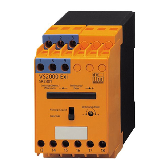
- Page 1 Operating instructions ENGLISH Control monitor VS2000 Exi PTB 01 ATEX 2075 ifm electronic Ltd. • Hampton, Middlesex TW12 2HD • Tel. 0208 / 213-0000...
-
Page 2: Table Of Contents
The operating instructions ... apply to all control monitors of type VS2000 Exi. The only difference between the individual units is the height of the permissible AC or AC/DC power supply which is indicated on the type label of the unit.. -
Page 3: Function And Features
2. Function and features The VS2000 Exi control monitor is designed to work with flow sensors of intrinsi- cally safe design Ex"i". It meets the requirements according to EN50014 and EN50020 (intrinsic safety "i"). The explosion group indicated on the unit as well as special conditions have to be taken into account according to EC type test certificate PTB 01 ATEX 2075. -
Page 4: Electrical Connection
In this case adhere to the distances between the units. The following applies to identical VS2000 Exi units: • Distance = 0 mm when operated with U (see Technical data / Operating volt- age). • Distance = at least 10 mm when operated with U +10%. - Page 5 Connection of sensors Max. permissible values of the control circuits for SN2301 ... SN2304: in the protection rating intrinsic safety [EEx ia] IIC and [EEx ia] IIB = 15.8 V Voltage = 92 mA / I = 47.2 mA Current = 680 mW Power in the protection rating intrinsic safety...
-
Page 6: Adjustment
5. Adjustment Row of LEDs - red LED is lit: flow below the switch point - yellow LED is lit: relay is energised, flow has reached the switch point - green LED is lit: flow above the switch point LED red - is lit in case of wire break or short circuit Selector switch medium (liquid/gas) Setting potentiometer for switch point... -
Page 7: Installation And Set-Up / Operation
7. Installation and set-up / operation After mounting, wiring and setting check the safe functioning of the unit In the case of wire break or short circuit of the sensor cable the relay "wire moni- toring" is de-energised and the red LED lights. After rectification of the fault the con- trol monitor is again ready for operation 8.