Table of Contents
Advertisement
Quick Links
Advertisement
Table of Contents

Related Manuals for Kobold MIK Series


Summary of Contents for Kobold MIK Series
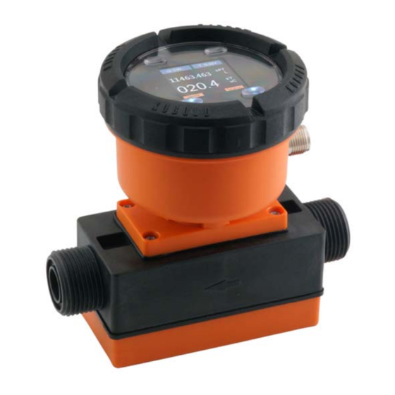
- Page 1 Operating Instructions Compact Magnetic-Inductive Flow Meter Model: MIK...
-
Page 2: Table Of Contents
1. Contents Contents ......................2 Note ......................4 Instrument Inspection ..................4 Regulation Use ..................... 5 Operating Principle ..................5 General ....................5 Minimum electrical conductivity / contained gases ......5 ... - Page 3 EU Declaration of Conformance ..............40 UK Declaration of Conformity..............41 Manufactured and sold by: Kobold Messring GmbH Nordring 22-24 D-65719 Hofheim Tel.: +49(0)6192-2990 Fax: +49(0)6192-23398 E-Mail: info.de@kobold.com Internet: www.kobold.com page 3 MIK K18/0323...
-
Page 4: Note
Please read these operating instructions before unpacking and putting the unit into operation. Follow the instructions precisely as described herein. The instruction manuals on our website www.kobold.com are always for currently manufactured version of our products. Due to technical changes, the instruction manuals available online may not always correspond to the product version you have purchased. -
Page 5: Regulation Use
5. Operating Principle 5.1 General The new KOBOLD flow meter Type MIK is used for measuring and monitoring smaller and medium-sized flow of conductivity liquids in pipes. The device operates according to the electromagnetic measuring method. According to Faraday’s Law of electromagnetic induction a voltage is induced in a conductor... -
Page 6: Deposits
5.3 Deposits Minor deposits on the measuring tube do not compromise the accuracy of measurement in general, as long as their conductivity does not seriously deviate from that of the fluid. In the case of fluids that have a tendency to deposit sediment, the measuring tube should be checked at regular intervals and cleaned if necessary. -
Page 7: Mechanical Connection
6. Mechanical Connection 6.1 Check operating conditions flow rate max. operating pressure max. operating temperature In general, the MIK is subjected to the same loads as the piping into which it is installed. The MIK should therefore be kept away from extreme loads, such as pressure surges with strong, dynamic pipe movements, vibrations in the proximity of centrifugal pumps, high temperature media, flooding etc. - Page 8 in- and outlet mounting top down avoid this mounting position page 8 MIK K18/0323...
-
Page 9: Electrical Connection
7. Electrical Connection 7.1 General Attention! Make sure that the voltage values of your system correspond with the voltage values of the measuring unit. Make sure that the supply wires are de-energised. Connect the supply voltage and the output signal to the plug PIN’s as stated below. -
Page 10: Mik
7.4 MIK-...F300; MIK-...L3x3 Connection example MIK-...L3x3 n.c. n.c. Signal Signal 7.5 MIK-...L443 Signal 7.6 MIK-...C30.. 7.7 MIK-...C34.. 0(4)-20 mA Switch Out 2 Switch Switch out 1 Out 1 page 10 MIK K18/0323... -
Page 11: Mik
7.8 MIK-...Ex4R, MIK-...Gx4R Cable connection MIK-...E14R MIK-...G14R Wire number Counter electronics Dosing electronics +24 V +24 V 4-20 mA 4-20 mA n. c. Control 1* Reset part quantity Control 2* Relay S1 Relay S1 Relay S1 Relay S1 Relay S2 Relay S2 Relay S2 Relay S2... -
Page 12: Mik
7.9 MIK-...C3T0 page 12 MIK K18/0323... -
Page 13: Operation
8. Operation The units are preset and after electrical connection ready for operation. 8.1 Switch point setting MIK-...S300, MIK-…S30D Switch setting Switch point Switch function deactivated 10 % of f.s. 20 % of f.s. 30 % of f.s. 40 % of f.s. 50 % of f.s. -
Page 14: Adjustments - Compact Electronics Mik
10. Adjustments – Compact Electronics MIK- ...C30/C34 Connect the compact electronics according to previous connection diagram and supply with the indicated power supply. After power on, the measuring range (end current) will be shown for 3 seconds. 10.1 Button function In the standard mode (measuring mode) : Press 3 sec. -
Page 15: Value Setting
10.3 Value setting From the main menu item (for example: switch point, " SPo "), press the "" button to set the value. The flow chart below illustrates the universal routine for changing individual parameters. [From the main menu item] 1. -
Page 16: Set-Up Mode
10.4 Set-up mode Compact electronics MIK-...C30.. 3 sec Code entering Value setting Swichting point 1 Value setting Switching point 2 Value setting Hysteresis Value setting Filter 7 Levels Value setting Contact 1 function Storing Frequency Contact 2 function Storing Changing code Value setting page 16 MIK K18/0323... - Page 17 Compact electronics MIK-...C34.. 3 sec Code entering Value setting Switching point Value setting Hysteresis Value setting Windowpoint Value setting Filter 7 levels Value setting Contact function Storing Frequency Start current 7sec Value setting End current 7sec Value setting MIK K18/0323 page 17...
-
Page 18: Main Menu Items
0-20 Start current selection 7sec Save 4-20 Changing code Value setting 10.5 Main menu items 10.5.1 Switching point The switching point is entered in the menu item " Spo, SP1, SP2 ". A setting value between 000 and 999 can be selected. This value can also include a decimal point. - Page 19 10.5.3 Window point (duo-point) As well as the switching point, it is also to define a " duo " (duo-point), the window point. This must be higher than the switching point. By using the window point and the switching point it is possible to monitor the measurement value in a certain range.
- Page 20 Flow Display bar (°C) LED on Hysteresis Time / t Flow Display bar (°C) LED on Hysteresis Window point LED on Switchpoint Hysteresis Time / t 10.5.5 Contact type The function of the transistor switching output is set in menu item " Con, Co1 or Co2 ".
-
Page 21: Device Status - Compact Electronics Mik
Empty Pipe or medium with insufficient conductivity of the medium conductivity is used. (>20 µs/cm) Error in the temperature Repair by KOBOLD Temp Sens Error measuring circuit Service required Flow measurement circuit Decrease flow rate Meas saturated... -
Page 22: Technical Information
13. Technical Information Operating instructions, data sheet, approvals and further information via the QR code on the device or via www.kobold.com 14. Order Codes Operating instructions, data sheet, approvals and further information via the QR code on the device or via www.kobold.com 15. -
Page 23: Disposal
16. Disposal Note! Avoid environmental damage caused by media-contaminated parts Dispose of the device and packaging in an environmentally friendly manner Comply with applicable national and international disposal regulations and environmental regulations. Batteries Batteries containing pollutants are marked with a sign consisting of a crossed-out garbage can and the chemical symbol (Cd, Hg, Li or Pb) of the heavy metal that is decisive for the classification as containing pollutants: 1. -
Page 24: Io-Link (Electronics Mik-C3T0 Only)
50 mA may be drawn from output 2 (OUT2) (current or binary output), otherwise the IO-Link master will be overloaded and malfunctions may occur. 17.2 Specification Manufacturer ID 1105 (dezimal), 0x0451 (hex) Manufacturer Kobold Messring GmbH IO-Link specification V1.1 Bitrate COM3 Minimum cycle time 1.1 ms... -
Page 25: Appendix
18. Appendix 18.1 IO-Link process data structure Process data length: 10 bytes Byte Data Format Factor Range Value number counter 0 - 3 Flow 32 Bit FloatT +/-1,4E-45 ... +/-3,4E+38 L/min 4 - 7 Volume 32 Bit FloatT +/-1,4E-45 ... +/-3,4E+38 L Temperature 12 Bit IntegerT... -
Page 26: Io-Link Diagnosis Information
18.2 IO-Link diagnosis information Event Event Device Code Code Name Type Definition Status [hex] [dec] 0x7710 30480 Short Circuit Error check installation Process Variable process data 0x8C10 35856 Warning Range Overrun uncertain Measurement Range 0x8C20 35872 Error check application ... - Page 27 0x185F 6239 EmptyPipe Warning no media in tube no temperature 0x1860 6240 Temp Sensor Error Error sensor attached 0x1861 6241 Measure Saturated Warning ADC out of range MIK K18/0323 page 27...
-
Page 28: Io-Link System Command Table
18.3 IO-Link system command table Command Command Command name (hex) (hex) Restore factory settings Reset MinMax Flow unused Reset MinMax Temperature Reset Part Volume Counter unused unused unused unused Start Simulation Flow unused Start Simulation Temperature Start Simulation Part Volume unused unused unused... -
Page 29: Io-Link Isdu Parameter Table
18.4 IO-Link ISDU parameter table Parameters that relate to the measured values of flow, temperature or volume must be entered in the basic units and, if necessary, converted beforehand. The basic units are: Flow: L/min Temperature: °C Volume: Liter Units conversion table Category: Flow Unit description... - Page 30 Max Value Min Value Access [hex] [Bytes] Type System See Table "Comand UInteg 0x0002 SystemCommand 1 W Codes" erT Product Identification (Vendor specific parameters) Kobold max. 0x0010 VendorName StringT R Messring 20 www.kobold.c max. 0x0011 VendorText StringT R om ...
- Page 31 (1) ‐ Flow Source for the lower (2) ‐ Volume UInteg 0x0105 LowerDisplay 2 1 R/W display (3) ‐ Temperature erT (4) ‐ Part Volume (1) ‐ Off Refresh intervall for 0x0106 DisplayRefreshTime 0,5 (2) ‐ Value 4 FloatT R/W the display [s] (3) ‐ MinMax (1) ‐ Off Function for left UInteg 0x010A LeftHotkeyFunction 0 (2) ‐ Value 1 R/W hotkey erT (3) ‐ MinMax (1) ‐ Flow Function for right (2) ‐ Volume UInteg 0x010B ...
- Page 32 If enabled (1) the analogoutput conforms with the NAMUR Standard OUT2AnalogNamurSta (1) ‐ NAMUR disabled UInteg 0x0124 NE42. If disabled (0) 1 1 R/W ndard (2) ‐ NAMUR enabled erT the analogoutput stays in his equivalent range (e.g. 4‐20mA) The value from the OUT2Analo slot used for the 0x0125 OUT2AnalogValue0mA 0,0 g MRS 4 FloatT R/W 0mA scaling point Value20mA [LPM/°C] The value from the OUT2Analo slot used for the 0x0129 OUT2AnalogValue4mA 0,0 g MRS ...
- Page 33 Controlinputfunction UInteg 0x0166 OUT1CtrlFunction ‐> Off or 0 1 0 1 R/W erT Memoryreset Output 2 (1) ‐ Flow Source for the (2) ‐ Volume UInteg 0x0177 OUT2Source 0 1 R/W output (3) ‐ Temperature erT (4) ‐ Part Volume (1) ‐ disabled (2) ‐ Alarm Output Configuration of the (2) ‐ 4‐20mA output ‐> (3) ‐ 0‐20mA UInteg 0x0178 OUT2Type 0 1 R/W 0‐20mA, Pulse, (4) ‐ 2‐10V erT ...
- Page 34 The value from the OUT2Analo OUT2AnalogValue20m slot used for the 0x0194 100,0 MRE g 4 FloatT R/W A 20mA scaling point Value0mA [LPM/°C] The value from the OUT2Analo slot used for the 0V 0x0198 OUT2AnalogValue0V 0,0 g MRS 4 FloatT R/W scaling point Value10V [LPM/°C] The value from the OUT2Analo slot used for the 2V 0x019C OUT2AnalogValue2V 0,0 g MRS 4 FloatT R/W scaling point ...
- Page 35 Timeout [s] for no 0x01EB DosingTimeout 0,5 10,0 0,5 4 FloatT R/W flow Saved dosing volume 0x01EF DosingCounter 0,0 999999,0 ‐999999,0 4 FloatT R counter stats Service Password for user UInteg 0x01F3 ServiceUserPassword service menu and 0 99999 0 4 R/W erT main menu ServiceUserMenuLock Whether main menu (1) ‐ not locked UInteg 0x01F7 0 1 R/W ...
- Page 36 Saved max flow 0x0328 MaxValueInSiUnit 0,0 999999,0 ‐999999,0 4 FloatT R value in SI unit [LPM] Volume counting type for a volume slot ‐> (1) ‐ absolute UInteg 0x0358 CountingType 0 1 R/W absolute or (2) ‐ bidirectional erT bidirectional (1) ‐ USER (2) ‐ L (3) ‐ mL UInteg 0x035D Unit Unit used for volume 1 (3)‐ m3 1 R/W erT (4) ‐ galUS (5) ‐ galUK (6) ‐ Barrel User Unit used for 0x035E ...
- Page 37 User Unit used for 0x0426 UserUnit 1,0 9999,9 0,001 4 FloatT R/W part volume Mode of the (1) ‐ Static Simulation: UInteg 0x043F SimMode 0 (2) ‐ Triangle 1 R/W Static, Triangle or erT (3) ‐ Monotonic Monotonic Value to start with 0x0440 SimStartValue 0,0 99999,99 ‐99999,99 4 FloatT R/W the simulation Incrementation 0x0444 SimIncrementValue value of the 10,0 99999,99 ‐99999,99 ...
- Page 38 19. Manufacturer’s declaration page 38 MIK K18/0323...
- Page 39 MIK K18/0323 page 39...
- Page 40 20. EU Declaration of Conformance We, KOBOLD Messring GmbH, Hofheim-Ts, Germany, declare under our sole responsibility that the product: Compact Magnetic-Inductive Flow Meter Model: MIK-… to which this declaration relates is in conformity with the standards noted below: EN 61326-1: 2022...
- Page 41 21. UK Declaration of Conformity We, KOBOLD Messring GmbH, Hofheim-Ts, Germany, declare under our sole responsibility that the product: Compact Magnetic-Inductive Flow Meter Model: MIK-… to which this declaration relates is in conformity with the standards noted below: BS EN 61326-1:2021 Electrical equipment for measurement, control and laboratory use.
Need help?
Do you have a question about the MIK Series and is the answer not in the manual?
Questions and answers