
Subscribe to Our Youtube Channel
Related Manuals for Kobold MAS Series


Summary of Contents for Kobold MAS Series
- Page 1 KOBOLD MAS Series Thermal Mass Flowmeters March 1997 r2_12-13 Part Number: IM-82 KOBOLD Instruments Inc 1801 Parkway View Drive · Pittsburgh, PA 15205 (412) 788-2830 · (800) 998-1020 · Fax (412) 788-4890...
-
Page 2: Introduction
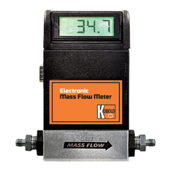
Model MAS-1100 Flowmeter with aluminum body and display. Model MAS-2100 Flowmeter with aluminum body and no display. Kobold Instruments’ MAS Series Flowmeters measure the mass flow rate of gases in ranges from 0-10 standard cubic centimeters per minute (SCCM) to 0-500 standard liters per minute (SLM). For most models, accuracy is 1.5% of full scale over a wide temperature... - Page 3 180° for easy viewing and can be removed for remote mounting on a front panel. The Kobold MAS directly monitors the mass flow rate of the gas. This means it measures molecular flow – the measurement quality of direct concern in most applications, such as human respiration, chemical processes, combustion, and heating or cooling.
-
Page 4: Principle Of Operation
MAS Instruction Manual The MAS Flowmeter is a transducer requiring a 12-15 VDC (24 VDC optional) external power source. A 0-5 VDC or optional 4-20 mA output singal linearly proportional to gas mass flow rate is provided for recording, data-logging, or control. A 9-Pin “D” sub- connector is provided for power input and signal output. -
Page 5: Specifications
SECT. A-A To change the flow range of your MAS, follow the instructions provided with the Kobold Model EL Laminar Flow Bypass Set and cut away the “gate(s)” leading to the right combination of laminar flow paths in one of the two bypasses. This procedure requires proper calibration facilities and minimal skill in electronics. - Page 6 MAS Instruction Manual UTPUT IGNAL Linear 0-5 VDC standard, 1000 ohms min. load impedance; 4-20 mA optional, 50 to 500 ohms loop resistance. OWER EQUIREMENTS 12-15 VDC nominal; 100 mA max (24 VDC optional, specify when ordering). CCURACY ± 1.5% of full scale including linearity over 15 to 25°C and 5 to 60 );...
- Page 7 MAS Instruction Manual ETTED ATERIALS Polyamide 6/6; 316 stainless steel; FKM “O”- 5% glass-filled rings standard, FFKM and silicone O-rings optional. EIGHT 2 lb. (0.9 kg) net; 3 lb. (1.4 kg) shipping. SIDE VIEW END VIEW BOTTOM VIEW Dimensions 4.16 5.38 6-32 X 0.15 DP.
-
Page 8: Options
MAS Instruction Manual Many options are available for your Kobold MAS. Please consult Kobold’s current Price List for the respective prices. Options (Optional) 4-20 mA output signal C( ) Cable assembly, specify cable type (round or ribbon) and length 1-5 Channel Power Supply, in NEMA Box, 115 VAC... -
Page 9: Installation
For our customers other than the USA, Canada and Mexico please call the distributor from whom you purchased your MAS or call our head office in Germany for the Kobold location nearest you: Germany 49(0)61-92-29-90 or Fax 49(0)61-92-23-398 Remove the packing slip from its envelope and verify that the carton contains all parts listed. -
Page 10: Mechanical Installation
MAS Instruction Manual CAUTION! The maximum pressure and temperature in the CAUTION! The maximum pressure and temperature in the CAUTION! The maximum pressure and temperature in the CAUTION! The maximum pressure and temperature in the CAUTION! The maximum pressure and temperature in the flow line in which your MAS is to be installed must not flow line in which your MAS is to be installed must not flow line in which your MAS is to be installed must not... - Page 11 MAS Instruction Manual Figure 2-1 Plumbing Requirements for Model’s 1100/2100 FLOW 5.0" 2.50" (127 mm) (63.5 mm) " NPT PIPE " NPT PIPE (10 DIAMETERS) (5 DIAMETERS) EXAMPLE: Cross Section INCORRECT CORRECT Avoid use of compression " NPT pipe for fitting on inlet of flow body.
-
Page 12: Electrical Connections
+24 VDC power at 100 mA. Connections Operating power input is via either the DC power jack or the 9-pin 2.5.1 “D” connector on the side of the enclosure. Kobold offers the Model 9-Pin “D”-Connector MAS-5000 single channel power supplies for single transducer Pin Assignments applications and the Model MAS-5100 for powering up to eight transducers through the "D"... - Page 13 MAS Instruction Manual Figure 2-3 Printed Circuit Board Input/Output Solder Pad Assignments (wires shown are typical) The following connection points can be made through the “D” connector or, in OEM applications, made through the circuit board solder pad connections. The display pad connections are shown for applications requiring remote mounting of the digital display.
-
Page 14: Remote Installation Of Digital Display
MAS Instruction Manual As shown in Figure 2-4, the digital display on your MAS may be 2.5.2 removed and mounted remotely on a front panel. The MAS Remote Installation of transducer is mounted at any convenient location in your system. Digital Display Remote installation is not recommended unless you possess the proper soldering tools and skills to accomplish the job. -
Page 15: Oem Electrical Connections
Using Kobold’s Single, of Kobold Instruments’ Single-Channel, Dual-Channel, or Flo- Dual, and Flo-Box™ Box (1-5 Channels) Electronics. The Kobold electronics will provide Electronics you with a selectable digital readout for each channel, input power, high, low, or window alarms, and optional flow totalization. -
Page 16: Operation
MAS Instruction Manual Quick operating instructions are given on the first page of this manual. OPERATION Following are important notes and comments regarding the Quick Operating Instructions. Quick Operating Instructions NOTE 1 R EFERENCING THE ATE TO THER EMPERATURE AND Notes to Operating RESSURE ONDITIONS... - Page 17 MAS Instruction Manual right most digits will blank and only the left-hand “1” will appear on the display. Overrange conditions are indicated by the display and/or output going to a high level, above the full scale range. After the overrange condition has been removed, it may take several seconds for the MAS to recover and resume normal operation.
- Page 18 MAS Instruction Manual Figure 3-1 Single Unit 4-20 Hookup Figure 3-2 Multiple Installation 4-20 Hookup Page 17...
-
Page 19: Maintenance
Calibrations may be scheduled once or twice yearly, depending on the accuracy to be maintained, or as needed. It is recommended that your MAS be returned to Kobold It is recommended that your MAS be returned to Kobold... -
Page 20: Sensor Tube
0.030 inch (.737-.762 mm) outside diameter rod or wire or with the Model CK Cleaning Stylet available from Kobold Instruments. To maximize the time response of your MAS, Kobold has designed the sensor tube with thin walls. Therefore, when cleaning, be... -
Page 21: Flow Calibration
“K”-factors and gas tables Calibration Procedure given in Appendix D. The standard 1.5% calibration of your MAS is best accomplished with the Kobold Instruments’ Series 100 Cal- Bench™. Flow recalibration is performed by using the following procedure. - Page 22 MAS Instruction Manual This completes the calibration procedure. To adjust linearity, go to STEP 4. STEP 4 A : First gain access to the printed DJUSTING INEARITY circuit board inside the MAS enclosure by using the procedure described in Section 2.5.3, OEM E .
-
Page 23: Flow Calibration Over A Different Flow Range And/Or Gas
Kobold Instruments. Appendix C is helpful in this regard. You must then use the K-factor tables in Appendix D. The next step is to procure from Kobold Instruments the Model EL Laminar Flow Bypass Set. This set of two patented Model EL LFE’s covers all ranges from 0-10 SCCM to 0-40 SLM, when the... -
Page 24: Troubleshooting
MAS Instruction Manual When it is suspected that your MAS is not operating correctly, a few simple checks can be made before dismantling for repair: TROUBLE- 1. Make sure there are no leaks in the line. SHOOTING 2. Check that all cables are plugged in and are in good condition. 3. - Page 25 Please call Customer Service Department, Technical Assistance, (412) 788-2830, Fax (412) 788- 4890. European customers can contact Kobold Messring GmbH for customer service and technical assistance at 49(0)61-92-29-90, Fax 49(0)61-92-23-398. Please have your Serial Number and Model Number when you call.
-
Page 26: Standard Servicing And Recalibration
R1 Standard Recalibration (1.5%) and Cleaning R2 Standard Recalibration (1.5%), Cleaning and Repair R3 Replacement Sensor and Standard Recalibration (1.5%) If you wish to have Kobold calibrate with a different flow range and/or gas, please take note of the following. NOTE 1 F ANGE The standard flow ranges given in Section 1.3, S... - Page 27 MAS Instruction Manual APPENDIX A Exploded View of MAS Transducers and Parts Lists Page 26...
-
Page 28: Aluminum Assembly High-Flow, Mas-1100/2100
MAS Instruction Manual Aluminum Assembly High-Flow, MAS-1100/2100 M82-0022 Page 27... -
Page 29: Aluminum Flowbody, High-Flow: Mas-1100/2100
MAS Instruction Manual Aluminum Flowbody High-Flo, MAS-1100/2100 M82–0017–X Parts List M82-0017–X Parts List M82-0017–X Parts List M82-0017–X Parts List M82-0017–X Parts List M82-0017–X ITEM DESCRIPTION 41-0175 Body, 820, Hi-Flow, Al 41-0176 Cap. End. 820. High Flow 40-0037 Holder. LFE. Mod 820 35-0084 Washer, Split, #06 35-0326... -
Page 30: Mas Assembly Mas-1000/2000
MAS Instruction Manual MAS Assembly MAS-1000/2000 M82–0023 Page 29... -
Page 31: Polyamide Flowbody: Mas-1000/2000
MAS Instruction Manual Polyamide Flowbody MAS-1000/2000 M82–0018 A Parts List M82-0018–X Parts List M82-0018–X Parts List M82-0018–X Parts List M82-0018–X Parts List M82-0018–X ITEM DESCRIPTION 42-0053 Body, 820, Black 40-0043 Screen. Mod 820 (for > 10 SLPM Flows) O-Ring, FKM 3-906 31-0001-906 42-0105 Adaptor. -
Page 32: Electronics Enclosure Sub-Assembly Mas
MAS Instruction Manual Electronics Enclosure Sub-Assembly MAS M82–0019–XXXX B Page 31... - Page 33 MAS Instruction Manual Parts List M82-0019–XXXX Parts List M82-0019–XXXX Parts List M82-0019–XXXX Parts List M82-0019–XXXX Parts List M82-0019–XXXX ITEM DESCRIPTION 42-0033 Encl, 820, Front, White 42-0034 Encl, 820, Back, White 52-0038-11 PCA, 820 Flow Meter: 110/220 VAC; 0-5 VDC 42-0038 Bracket, PCB, 820 42-0044 Slides, Zero &...
-
Page 34: Sensor Compartment Assembly: Mas
MAS Instruction Manual Sensor Compartment Assembly: MAS M82–0020–X B Page 33... - Page 35 MAS Instruction Manual Parts List M82-0020–X Parts List M82-0020–X Parts List M82-0020–X Parts List M82-0020–X Parts List M82-0020–X ITEM DESCRIPTION 41-0207 Plate, Sensor Mounting (Die Cast) 41-0173 Heat Sink (Die Cast) 43-0037-01 Sensor, Flow Capillary 41-0171 Bushing, Sensor O-Ring (Die Cast) 41-0170 Plate, Sensor Ring, 820 (Die Cast) 35-0130...
-
Page 36: Stainless Steel Low Flow Dimensional Drawing
MAS Instruction Manual Stainless Steel Low Flow Dimensional Drawing Side View Tables " O.D. Tube Fitting Type "-18 Thd.) Comp. (male) (male) Dim.“L” Bottom View Outlet End View Page 35... -
Page 37: Stainless Steel Medium Flow Dimensional Drawing
MAS Instruction Manual Stainless Steel Medium Flow Dimensional Drawing Tables Side View Flow Range 0-20 0-30 0-50 Tube O.D., ", " ", " ", " Inches Flow Range, 0.706 1.06 1.77 SCFM Tube O.D., " " " Inches Fitting Type "... -
Page 38: Stainless Steel High Flow Dimensional Drawing
MAS Instruction Manual Stainless Steel High Flow Dimensional Drawing Side View Tables Flow Range 0-100 0-200 0-300 Tube O.D., ", " ", " " Inches Flow Range, 3.53 7.06 10.6 SCFM Tube O.D., " " " Inches Fitting Type " "... -
Page 39: B Conversion Of Flow Rate To Other T And P Conditions
MAS Instruction Manual The flow rate of your MAS is referenced to certain “standard” APPENDIX B conditions of temperature and pressure. Unless otherwise specified Conversion of Flow in your order, these standard conditions are 21°C (70°F) and 760 Rate to Other T and P mm of mercury (1 atmosphere). -
Page 40: K-Factors And Gas Tables
MAS Instruction Manual The following tables provide K-factors and thermodynamic APPENDIX C properties of gases commonly used with mass flow controllers and K Factors and meters. The purpose of these tables is two-fold: Gas Tables 1. Calibrating an “actual” gas with a reference gas. This is For a Single Gas particularly useful if the actual gas is not a common gas or if it is a so-called “nasty”... - Page 41 The value from the tables is preferred because in many cases it was obtained by experiment. Kobold calibrates every MAS mass flowmeter and controller with primary standards using the actual gas or a molecularly equivalent reference gas. The calibration certificate accompanying your MAS...
-
Page 42: For Dual-Gas Mixtures
MAS Instruction Manual will cite the reference gas used. When a reference gas is used, the actual flow rate will be within 2-4% of the calculated flow rate. EXAMPLE 1: A MAS is calibrated for nitrogen (N2), and the flow rate is 1000 SCCM for a 5.000 VDC output signal. - Page 43 MAS Instruction Manual where: ρ ρ ˙ / ˙ ρ ρ ˙ / ˙ The equivalent value of N is: ˙ / ˙ ˙ / ˙ The equivalency relationships for r, C , and N for mixtures of more than two gases have a form similar to the dual-gas relationship given above.
- Page 44 MAS Instruction Manual Actual Gas Chemical Ref. KFactor KFactor Density Elastomer DRAWING NO. REV. SHEET Symbol Rel. to Relative (Cal/g) (g/ l ) O-Ring* Valve ° Ref. Gas Seat 99-0224 1 of 3 12/95 Acetylene .4036 1.162 1.00 .240 1.293 Allene (Propadiene) ..43 .352...
- Page 45 MAS Instruction Manual Actual Gas Chemical Ref. KFactor KFactor Density Elastomer DRAWING NO. REV. SHEET Symbol Rel. to Relative (Cal/g) (g/ l ) O-Ring* Valve ° 99-0224 2 of 3 Ref. Gas Seat 12/95 Dimeyl Ether .3414 2.055 2,2-Dimethylpropane .3914 3.219 Ethane .4097 1.342 Ethanol...
- Page 46 MAS Instruction Manual Actual Gas Chemical Ref. KFactor KFactor Density Elastomer DRAWING NO. REV. SHEET Symbol Rel. to Relative (Cal/g) (g/ l ) O-Ring* Valve ° Ref. Gas Seat 99-0224 3 of 3 12/95 Nitrogen Trifluoride .1797 3.168 Nitrosyl Chloride NOCl .1632 2.920 Nitrous Oxide...
- Page 47 MAS Instruction Manual Page 46...
-
Page 48: Table Of Contents
2.5.1 9-Pin “D” Connector Pin Assignments ......11 2.5.2 Remote Installation of Digital Display ......13 2.5.3 OEM Electrical Connections ..........14 2.5.4 Using Kobold’s Single, Dual, and Flo-Box™ Electronics ... 14 3 OPERATION ................15 3.1 Quick Operating Instructions ..........15 3.2 Notes to Operating Instructions .......... -
Page 49: Gas Tables
MAS Instruction Manual INDEX OF APPENDIX Aluminum Assembly, High-Flow: MAS-1100/2100 ....27 Aluminum Flowbody, High-Flow: MAS-1100/2100 ....28 MAS Assembly: MAS-1000/2000 ..........29 Polyamide Flowbody: MAS-1000/2000 ........30 Electronics Enclosure Sub-Assembly: MAS ......31-32 Sensor Compartment Assembly: MAS ....... 33-34 Stainless Steel Low Flow Dimensional Drawing ..... - Page 50 CAUTION! Any application whatsoever related to human CAUTION! Any application whatsoever related to human CAUTIONS! respiration must have the written consent of Kobold respiration must have the written consent of Kobold respiration must have the written consent of Kobold respiration must have the written consent of Kobold respiration must have the written consent of Kobold Instruments Inc.
- Page 51 (10 kg/cm gauge) or 150°F = 65.556°C. 2. Apply power to your MAS. If you are using the Kobold MAS- 5000 power supply, plug the power supply into line power and the connector into the input power jack on the side of your MAS.
- Page 52 MAS Instruction Manual For example, if you have a 0-5 VDC output signal, 5.00 VDC is the output signal for the full scale listed on your MAS; 2.50 VDC is for one-half of full scale; and 0.00 VDC is for zero flow. On the other hand, if you have 4-20 mA output signal, 20.00 mA is the output signal for the full scale;...
- Page 53 Kobold Instruments Inc. The information contained in this manual is subject to change without notice.
- Page 54 MAS Instruction Manual Page 54...
Need help?
Do you have a question about the MAS Series and is the answer not in the manual?
Questions and answers