Table of Contents
Advertisement
Quick Links
Advertisement
Table of Contents

Subscribe to Our Youtube Channel
Related Manuals for Kobold MIM Series


Summary of Contents for Kobold MIM Series
- Page 1 Operating Instructions Electromagnetic Flowmeter Model: MIM...
-
Page 2: Table Of Contents
MIM- We don’t accept warranty and liability claims neither upon this publication nor in case of improper treatment of the described products. The document may contain technical inaccuracies and typographical errors. The content will be revised on a regular basis. These changes will be implemented in later versions. - Page 3 MIM- Manufactured and sold by: Kobold Messring GmbH Nordring 22-24 D-65719 Hofheim Tel.: +49(0)6192-2990 Fax: +49(0)6192-23398 E-Mail: info.de@kobold.com Internet: www.kobold.com MIM K02/1217 page 3...
-
Page 4: Note
MIM- 2. Note Please read these operating instructions before unpacking and putting the unit into operation. Follow the instructions precisely as described herein. The devices are only to be used, maintained and serviced by persons familiar with these operating instructions and in accordance with local regulations applying to Health &... -
Page 5: Environment
(Electromagnetic Compatibility). 6. Operating principle General The new KOBOLD MIM Flowmeter is designed to measure and monitor small and medium flows of conductive fluids in piping. The device works on the magnetic-inductive measuring principle. According to Faraday's law of induction, a voltage is induced in a conductor moving in a magnetic field. -
Page 6: Deposits
MIM- Deposits Minor deposits on the measuring tube generally do not affect the measuring accuracy unless their conductivity deviates significantly from the liquid. For liquids that have a tendency to deposit, periodically inspect the meter tube and, if necessary, clean it. Measuring electrodes The MIM uses electrodes with galvanic tapping. -
Page 7: Mechanical Connection
MIM- 7. Mechanical connection Check operating conditions flow rate max. operating pressure max. operating temperature In general, MIM is subjected to the same loads as the piping into which it is installed. The MIM should therefore be kept away from extreme loads, such as pressure surges with strong, dynamic pipe movements, vibrations in the proximity of centrifugal pumps, high temperature media, flooding etc. - Page 8 MIM- Inlet and outlet run Installation from top to bottom avoid these installation locations Gas bubbles, particle Free outlet page 8 MIM K02/1217...
-
Page 9: Electrical Connection
MIM- 8. Electrical Connection 8.1 General Attention! Make sure that the voltage values of your system correspond with the voltage values of the measuring unit. Make sure that the supply wires are de-energised. Connect the supply voltage and the output signal to the plug PIN’s as stated below. -
Page 10: Pin Assignment
MIM- Pin assignment Configurable output functions: Out 1 Out 2 analogue output 4-20 mA analogue output 4-20 mA analogue output 0-20 mA analogue output 0-20 mA analogue output 0-10 V analogue output 0-10 V alarm output alarm output pulse output pulse output frequency output frequency output... -
Page 11: Operation And Menu Structure
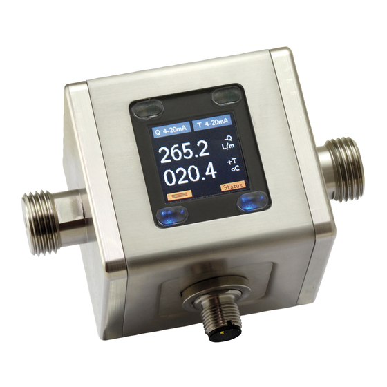
MIM- 9. Operation and menu structure General 9.1.1 Operation of the optical buttons Deactive optical button Optical button active An optical button is located at each corner of the TFT display. The operability of the respective buttons is signaled by blue backlighting; therefore non-backlit buttons are disabled and cannot be operated. -
Page 12: Measuring Mode
MIM- function key symbol designation Measuring mode menu mode Menu scroll up / Increase the number value for numeric value input Menu level lower / forward forward (last menu level: Save value) Menu function: menu backward level higher / back (last step: exit menu) Measuring mode After applying the supply voltage, the device starts in measuring mode. - Page 13 MIM- Measurement Mode Display Layout 'Single' The measurement variables are represented by their corresponding symbols: The outputs and their status are shown on the display as follows: The measured variables flow, temperature and volume counter can in principle be assigned to each output function. The assignment of the respective output is indicated by the display of the symbol of the measuring variable.
- Page 14 MIM- Measurement Mode Display Layout 'Dual' 9.2.1 Display area of the flow meters The number of digits displayed on the volume counter display (partial and total volumetric counters) is limited to max. 8 digits. The partial and total volumetric meters therefore have a smaller font size than the flow and temperature display. If the 8-digit display range of the meter is exceeded, this is indicated by the display of 8 minus characters (--------).
-
Page 15: Menu Mode
MIM- Menu Mode In menu mode, all device parameters can be set. The individual parameters are arranged in menu groups by function. While the menu mode is activated, the signal processing and the outputs are still active in the background. However, all display parameters and outputs are updated after exiting the menu mode or in the measuring mode. -
Page 16: Device Configuration
The flowmeter MIM is pre-configured in factory. Changing the parameters "Measuring range" and "Sensor constant" or "K factor" is therefore not permitted. The adjustment of these parameters is only possible on the part of Kobold- factory. In the event of subsequent changes to volume or throughput units, the dependent parameters are converted and adjusted accordingly. -
Page 17: Overview Of The Menu Functions / Device Parameters
MIM- 10.2 Overview of the menu functions / device parameters The Kobold flowmeter MIM gives user the opportunity to make the parameterization easily via the settings menu. In the following table, the menu structure is structured by level. Using this table, each parameter and function of the device can be set and configured. - Page 18 MIM- Sub- Sub- Menu Parameter Subparameter Default Sublevel parameter parameter Description Value range level level level 1 value level 2 level 3 Function sets function of Limit/Window Limit alarm output Output Type List sets characteristic NPN/PNP/PP selection of output Switch sets switching NO/NC Function...
- Page 19 Factory reset Yes/No n.A. n.A. to factory settings Service locks the menu n.A. entry using same Lock Menu password as set Unlock under 'Change Lock/Unlock Password' Factory Password protected Service Device Kobold Logo with Firmware version Status MIM K02/1217 page 19...
-
Page 20: Display
MIM- 10.3 Display 10.3.1 Refresh Parameter "Refresh" defines the time interval within which the measuring variables are displayed. The state of the outputs (current output, voltage output, frequency output) is also recalculated after the measuring time has expired. The "Refreshrate" can be increased in steps of 0.5 sec. to 10 sec. An increase in the refresh rate time causes on one hand an increased "filtering"... - Page 21 MIM- 10.4.1 Flow 10.4.1.1 Unit The displayed unit for the flow measurement can be selected from various predefined standard units. It is also possible to define a user-defined unit ("user"), here the "user unit" must be in liters / min. be programmed. e.g.
- Page 22 MIM- 10.4.3 Temperature 10.4.3.1 Unit The displayed unit for the temperature measurement can be selected from various default units. It is also possible to define a user-defined unit ("user"), in which case the "user unit" must be programmed in ° C. e.g.
-
Page 23: Outputs
MIM- 10.5 Outputs The MIM flowmeter provides a total of 2 outputs that are freely configurable. The configuration of the outputs (output 1 and output 2) is done via a wizard function. The wizard function guides the user step by step through all necessary settings. Steps: •... - Page 24 MIM- Window function: The switching output is active if the current flow measured value is outside a window, which is formed by the "switching threshold" and the "lower threshold". The monitored window decreases in each case by the amount of the "hysteresis". If the switching output is to be active within the window, the parameter "switching function"...
- Page 25 MIM- 10.5.1.6 Hysterese The appropriate setting of the "hysteresis" parameter ensures that the switching outputs do not switch on and off continuously when the current measured value fluctuates around the switching threshold. The hysteresis value should therefore always be greater than the real measured value fluctuations. As a result, a targeted suppression can be achieved.
- Page 26 MIM- 10.5.3 Pulse output The MIM flowmeter provides a scalable pulse output. When the pulse output is activated, the incoming volume is converted to the output pulse train. The pulse width of the output pulse is adjustable in the range of 1 ms to 20,000 ms. The electrical output type of the pulse output is push-pull, therefore HIGH and LOW are actively switched through at the output.
-
Page 27: User Service
MIM- Since the measuring range end value is set at the factory, the user should, when configuring the pulse output, carry out a computational check to see whether the upper condition is fulfilled. The pulse output only takes place in measuring mode, while the menu mode is active no pulses are given. -
Page 28: Service / Factory Service
(> 20 μs / cm) Temp Sens Error Error in the temperature Repair by KOBOLD Service measuring circuit necessary Meas saturated Flow measuring circuit Reduce flow rate... -
Page 29: Device Default Settings
MIM- 10.9 Device default settings The flowmeter-MIM is delivered from the factory with following settings: Display – Dual Upper display – Flow Lower display – Temperature Out 1: Q 4-20 mA Out 2: T 4-20 mA MIM K02/1217 page 29... -
Page 30: Technical Information
MIM- 11. Technical Information Measurement process: electromagnetic Range: see order details Media: conductive fluids Minimum conductivity: ≥20 µS/cm 70 mm 2 /s Max. medium viscosity: Max. pressure: 16 bar Accuracy: <±(0.8% of reading+ 0.5% of full scale)* Repeatability: ±0.2% of full scale Temperature measurement of media: PT1000, range -20 °C …+70 °C... -
Page 31: Order Codes
MIM- Frequenzy output Push-Pull, freely scaleable, Overflow frequency adjustable Alarm output: NPN, PNP, Push-Pull, output) configurable max. 30 V max. 200 mA short-circuit proof Analogue output: active, 3 wire, 0(4)-20 mA, max. load 500 Ω or 0-10 V DC , (R i = 500 Ω) Electrical connection: plug M12x1, 4-pin * Under reference conditions: media temperatur: 15 °C ... -
Page 32: Dimensions
MIM- 13. Dimensions [mm] page 32 MIM K02/1217... -
Page 33: Eu Declaration Of Conformance
MIM- 14. EU Declaration of Conformance We, KOBOLD Messring GmbH, Hofheim-Ts, Germany, declare under our sole responsibility that the product: Electromagnetic Flowmeter Model: MIM-... to which this declaration relates is in conformity with the standards noted below: EN 61326-1:2013 Elektrische Mess-, Steuer-, Regel- und Laborgeräte – EMV-...
Need help?
Do you have a question about the MIM Series and is the answer not in the manual?
Questions and answers