
Related Manuals for Kobold DUK


Summary of Contents for Kobold DUK
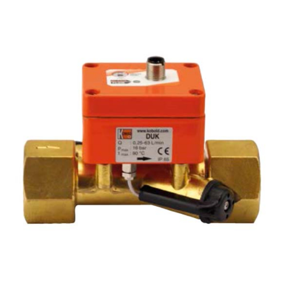
- Page 1 Operating Instructions Ultrasonic Flowmeter/ -Monitor/ -Counter/ -Dosing Unit Model: DUK...
-
Page 2: Table Of Contents
Use of media other than water (only option -C3T0) ......10 Adjustment – Compact Electronics DUK-...C3T0 ........10 Device status - compact electronics DUK-...C3T0 ........11 Maintenance ....................11 Technical Information .................. 12 ... - Page 3 Manufactured and sold by: Kobold Messring GmbH Nordring 22-24 D-65719 Hofheim Tel.: +49 (0)6192-2990 Fax: +49(0)6192-23398 E-Mail: info.de@kobold.com Internet: www.kobold.com DUK K14/1122 page 3...
-
Page 4: Note
Please read these operating instructions before unpacking and putting the unit into operation. Follow the instructions precisely as described herein. The instruction manuals on our website www.kobold.com are always for currently manufactured version of our products. Due to technical changes, the instruction manuals available online may not always correspond to the product version you have purchased. -
Page 5: Regulation Use
The user assumes all risk for such usage. 5. Operating Principle 5.1 General The new KOBOLD type DUK flow meters are used for the measurement, monitoring, metering and dosing of low viscosity aqueous fluids. The devices work on the principle of the difference in running times. -
Page 6: Mechanical Connection
max. operating pressure max. operating temperature In general, the DUK is subjected to the same loads as the piping into which it is installed. The DUK should therefore be kept free from extreme loads, such as pressure surges with strong, dynamic pipe movements, vibrations in the proximity of centrifugal pumps, high temperature media, flooding etc. - Page 7 In-/Outlet Runs Mounting from top to bottom avoid these installation areas Gas bubbles Particle Free outlet DUK K14/1122 page 7...
-
Page 8: Electrical Connection
Make sure that the supply wires are de-energised. Connect the supply voltage and the output signal to the plug PIN´s as stated below. We recommend the use of wires with cross sectional area of min. 0,25 mm². 7.2 DUK-...S300 Output Output Common Output 7.3 DUK-...S30D... -
Page 9: Duk
7.4 DUK-...F3x0; DUK-...L3x3 Connection example DUK-...L3x3 n.c. n.c. Signal Signal 7.5 DUK-...L443 Signal 7.6 DUK-...C3T0.. DUK K14/1122 page 9... -
Page 10: Operation
Flow below switch point: DUO-LED red 8.2 Use of media other than water (only option -C3T0) The DUK-...C3T0 is able to measure viscous media up to a maximum viscosity of 68 mm /s. However, this must be a homogeneous Newtonian liquid, but not necessarily based on water. -
Page 11: Device Status - Compact Electronics Duk
10. Device status - compact electronics DUK-...C3T0 display text error type display color description debugging functional limitation Measuring tube not or only Fill the measuring tube Meas Error orange completely with medium partially filled or stationary air or Flush out air bubbles... -
Page 12: Technical Information
12. Technical Information Operating instructions, data sheet, approvals and further information via the QR code on the device or via www.kobold.com 13. Order Codes Operating instructions, data sheet, approvals and further information via the QR code on the device or via www.kobold.com 14. -
Page 13: Disposal
(Cd, Hg, Li or Pb) of the heavy metal that is decisive for the classification as containing pollutants: 1. „Cd" stands for cadmium 2. „Hg" stands for mercury 3. „Pb" stands for lead 4. „Li" stands for lithium Electrical and electronic equipment DUK K14/1122 page 13... -
Page 14: Io-Link - Compact Electronics Duk
16. IO-Link – compact electronics DUK-...C3T0 16.1 IO-Link function The DUK-XXXXXC3T0 flow meter has an IO-Link communication interface as standard. The process and diagnostic data can be accessed directly via this interface and the device can be parameterized. Output 1 is factory configured for IO-Link function. If the IO-Link communication mode is active, the "IOLINK"... -
Page 15: Appendix - Compact Electronics Duk
17. Appendix - Compact electronics DUK-...C3T0 17.1 IO-Link process data structure Process data length: 10 bytes Byte Data Format Factor Range Value number counter +/-1,4*10-45 ... +/- 0 - 3 Flow 32 Bit FloatT L/min +/-1,4*10-45 ... +/- 4 - 7... -
Page 16: Io-Link Diagnostic Information
Flow Underflow underflow range 0x1842 6210 Warning Underrun underrun Temperature MRE measuring range 0x1847 6215 Warning Overrun overrun Temperature MRS measuring range 0x1848 6216 Warning Underrun underrun Temperature overflow range 0x1849 6217 Warning Overflow Overrun overrun page 16 DUK K14/1122... - Page 17 Temp Sensor Warning sensor broken wire Too many jumps 0x1863 6243 Medium Warning Warning in ultrasonic measurement Checksum of 0x1864 6244 NVM Error Warning NVM is wrong Ultrasonic signal 0x1865 6245 Signal Warning Warning is very attenuated DUK K14/1122 page 17...
-
Page 18: Io-Link System Command Table
Start Simulation Flow unused Start Simulation Temperature Start Simulation Part Volume unused unused unused unused Stop Simulation Flow unused Stop Simulation Temperature Stop Simulation Part Volume unused unused unused unused Events Handling ON Events Handling OFF page 18 DUK K14/1122... -
Page 19: Io-Link Isdu Parameter Table
1 m3 = 1000 L galUS US gallons 1 galUS = 3.7854 L galUK UK gallons 1 galk = 4.54609 L barrel Barrel (US) 1 barrel = 158.99 L USER User unit 1 user unit = USER * L DUK K14/1122 page 19... - Page 20 (1) ‐ Landscape Orientation of (2) ‐ Portrait Flip UInteg 0x0100 DisplayOrientation 1 1 R/W display (3) ‐ Landscape Flip erT (4) ‐ Portrait (1) ‐ single UInteg 0x0103 DisplayLayout Single or dual layout 1 1 R/W (2) ‐ dual erT (1) ‐ Flow Source for the upper (2) ‐ Volume UInteg 0x0104 UpperDisplay 0 1 R/W display (3) ‐ Temperature erT (4) ‐ Part Volume page 20 DUK K14/1122...
- Page 21 1,0 (MRE‐MRS) 0,0 4 FloatT R/W [LPM/°C] for the alarmoutput How many times the OUT2AlarmSuppressio threshold must be UInteg 0x0121 0 60 0 1 R/W nFactor hit in order to switch erT the alarm output for which direction (1) ‐ Up OUT2AlarmSuppressio UInteg 0x0122 the suppression 0 (2) ‐ Down 1 R/W nDirection erT factor is used (3) ‐ Both DUK K14/1122 page 21...
- Page 22 0x015B OUT2FrequencyatFS 500 1000 50 2 R/W for the output [Hz] erT The overflow OUT2FrequencyOverfl UInteg 0x015D frequency of the 1 100 0 1 R/W ow erT max frequency [%] The value from the OUT2Frequ OUT2FrequencyValue0 slot used for the 0Hz 0x015E 0,0 encyValue MRS 4 FloatT R/W Hz scaling point MaxHz [LPM/°C] page 22 DUK K14/1122...
- Page 23 (1) ‐ Up OUT2AlarmSuppressio UInteg 0x0189 the suppression 0 (2) ‐ Down 1 R/W nDirection erT factor is used (3) ‐ Both If enabled (1) the analogoutput conforms with the NAMUR Standard OUT2AnalogNamurSta (1) ‐ NAMUR disabled UInteg 0x018B NE42. If disabled (0) 1 1 R/W ndard (2) ‐ NAMUR enabled erT the analogoutput stays in his equivalent range (e.g. 4‐20mA) DUK K14/1122 page 23...
- Page 24 1 R/W ow erT max frequency [%] OUT2F The value from the requ OUT2FrequencyValue0 slot used for the 0Hz 0x01C5 0,0 encyVa MRS 4 FloatT R/W Hz scaling point lue [LPM/°C] MaxHz The value from the OUT2FrequencyValue slot used for the max OUT2Freque 0x01C9 100,0 MRE 4 FloatT R/W MaxHz Hz scaling point ncyValue0Hz [LPM/°C] page 24 DUK K14/1122...
- Page 25 16 StringT R eKey XXXXXXXXXXX Flow Cut off for flow value 0x02F5 CutOff 0,0 MRE 0.0 4 FloatT R/W [LPM] (1) ‐ USER (2) ‐ L/m (3) ‐ mL/m (4) ‐ L/h (4)‐ m3/h UInteg 0x02F9 Unit Unit used for flow 1 (5) ‐ galUS/m 1 R/W erT (6) ‐ galUS/h (7) ‐ galUK/m (8) ‐ galUK/h (9) ‐ L/s (10) ‐ mL/s DUK K14/1122 page 25...
- Page 26 99 Incrementation 99999, 0x03E0 SimIncrementValue value of the 10,0 ‐99999,99 4 FloatT R/W 99 simulation [°C] Number of intervals UInteg 0x03E4 SimNumberIntervals 20 65000 1 2 R/W to simulation erT Timinig in ms UInteg 0x03E6 SimTimingIntervals between intervals 50 50000 10 2 R/W erT [ms] page 26 DUK K14/1122...
- Page 27 R/W to simulation erT Timinig in ms UInteg 0x044A SimTimingIntervals 50 50000 10 2 R/W between intervals erT Saved part volume 999999 0x044C ValueInSiUnit 0,0 ‐999999,0 4 FloatT R value in SI unit ,0 Legend: MRE - Measuring Range End MRS - Measuring Range Start DUK K14/1122 page 27...
-
Page 28: Manufacturer's Declaration
18. Manufacturer’s declaration page 28 DUK K14/1122... - Page 29 DUK K14/1122 page 29...
-
Page 30: Eu Declaration Of Conformance
19. EU Declaration of Conformance We, KOBOLD Messring GmbH, Hofheim-Ts, Germany, declare under our sole responsibility that the product: Ultrasonic Flowmeter/ -Monitor/ -Counter/ -Dosing Unit Model: DUK-… to which this declaration relates is in conformity with the standards noted below:... -
Page 31: Declaration Of Conformity
20. UK Declaration of Conformity We, KOBOLD Messring GmbH, Hofheim-Ts, Germany, declare under our sole responsibility that the product: Ultrasonic Flowmeter/ -Monitor/ -Counter/ -Dosing Unit Model: DUK-… to which this declaration relates is in conformity with the standards noted below: ...
Need help?
Do you have a question about the DUK and is the answer not in the manual?
Questions and answers