Table of Contents
Advertisement
Quick Links
Advertisement
Table of Contents

Related Manuals for Kobold MIM Series


Summary of Contents for Kobold MIM Series
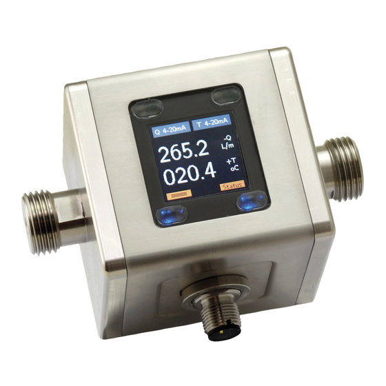
- Page 1 Operating Instructions Electromagnetic Flowmeter Model: MIM...
-
Page 2: Table Of Contents
MIM- We don’t accept warranty and liability claims neither upon this publication nor in case of improper treatment of the described products. The document may contain technical inaccuracies and typographical errors. The content will be revised on a regular basis. These changes will be implemented in later versions. - Page 3 IO Link ISDU parameter table ............51 Manufacturer’s declaration ................62 EU Declaration of Conformance ..............63 Manufactured and sold by: Kobold Messring GmbH Nordring 22-24 D-65719 Hofheim Tel.: +49(0)6192-2990 Fax: +49(0)6192-23398 E-Mail: info.de@kobold.com Internet: www.kobold.com MIM K10/0419 page 3...
-
Page 4: Note
MIM- 2. Note Please read these operating instructions before unpacking and putting the unit into operation. Follow the instructions precisely as described herein. The devices are only to be used, maintained and serviced by persons familiar with these operating instructions and in accordance with local regulations applying to Health &... -
Page 5: Instrument Inspection
MIM- 3. Instrument Inspection Instruments are inspected before shipping and sent out in perfect condition. Should damage to a device be visible, we recommend a thorough inspection of the delivery packaging. In case of damage, please inform your parcel service / forwarding agent immediately, since they are responsible for damages during transit. -
Page 6: Operating Principle
MIM- 6. Operating principle 6.1 General The new KOBOLD MIM Flowmeter is designed to measure and monitor small and medium flows of conductive fluids in piping. The device works on the magnetic-inductive measuring principle. According to Faraday's law of induction, a voltage is induced in a conductor moving in a magnetic field. -
Page 7: Mechanical Connection
MIM- 7. Mechanical connection 7.1 Check operating conditions flow rate max. operating pressure max. operating temperature In general, MIM is subjected to the same loads as the piping into which it is installed. The MIM should therefore be kept away from extreme loads, such as pressure surges with strong, dynamic pipe movements, vibrations in the proximity of centrifugal pumps, high temperature media, flooding etc. - Page 8 MIM- Inlet and outlet run Installation from top to bottom avoid these installation locations Gas bubbles, particle Free outlet page 8 MIM K10/0419...
-
Page 9: Electrical Connection
MIM- 8. Electrical Connection 8.1 General Attention! Make sure that the voltage values of your system correspond with the voltage values of the measuring unit. Make sure that the supply wires are de-energised. Connect the supply voltage and the output signal to the plug PIN’s as stated below. - Page 10 MIM- Connection example: OUT2: analogue output 4-20 mA OUT1: analogue output 0-10 V page 10 MIM K10/0419...
-
Page 11: Operation And Menu Structure
MIM- 9. Operation and menu structure 9.1 General 9.1.1 Operation of the optical buttons Deactive optical button Optical button active An optical button is located at each corner of the TFT display. The operability of the respective buttons is signaled by blue backlighting; therefore non-backlit buttons are disabled and cannot be operated. -
Page 12: Measuring Mode
MIM- function key symbol designation Measuring mode menu mode value input Menu level lower / forward forward (last menu level: Save value) Menu function: menu backward level higher / back (last step: exit menu) 9.2 Measuring mode After applying the supply voltage, the device starts in measuring mode. In this mode, the measured values of the respective measuring variables are continuously recorded;... - Page 13 MIM- Measurement Mode Display Layout 'Single' The measurement variables are represented by their corresponding symbols: Mesuring variables Menu entry Description Symbol Flow Flow rate Volume Accumulated totalizer Temperature Medium temperature Part volume Partial totalizer The outputs and their status are shown on the display as follows: Output function OUT1/2 Symbol Representation...
- Page 14 MIM- Measurement Mode Display Layout 'Dual' Out 1 configured as switching output Out 2 configured as analogue output 4-20 mA pushpull and assigned to flow and assigned to temperature Font white: MV within MR Measuring variables with sign for direction Font yellow: 100% MR <=MV <=OverFlow Font red: MV OverFlow Unit for measuring variable...
-
Page 15: Menu Mode
MIM- 9.3 Menu Mode In menu mode, all device parameters can be set. The individual parameters are arranged in menu groups by function. While the menu mode is activated, the signal processing and the outputs are still active in the background. However, all display parameters and outputs are updated after exiting the menu mode or in the measuring mode. -
Page 16: Device Configuration
The flowmeter MIM is pre-configured in factory. Changing the parameters "Measuring range" and "Sensor constant" or "K factor" is therefore not permitted. The adjustment of these parameters is only possible on the part of Kobold- factory. In the event of subsequent changes to volume or throughput units, the dependent parameters are converted and adjusted accordingly. -
Page 17: Display
MIM- 10.3 Display 10.3.1 Refresh Parameter "Refresh" defines the time interval within which the measuring variables are displayed. The "Refreshrate" can be increased in steps of 0.5 sec. to 10 sec. An increase in the refresh rate time causes an increased "filtering" of the display value. - Page 18 MIM- The called hotkey function remains permanently activated and can only be left by pressing the key . A direct reset function is available for the MIN / MAX measured value function and the partial quantity counter. 10.3.6 Key sensitivity The sensitivity of the keys can be adjusted by setting the key sensitivity.
-
Page 19: Measurement
MIM- Parameter table Display Sub- Sub- Sub- Default Default Parameter para- para- para- Value range/ Sublevel Description value value level meter meter meter value list level 1 level 2 level 3 Sets the display refresh Refresh value input 0.5-10 sec 0.5 sec rate Rotates the display 90 °... - Page 20 MIM- 10.4.1 Flow 10.4.1.1 Unit The displayed unit for the flow measurement can be selected from various predefined standard units. It is also possible to define a user-defined unit ("user"), here the "user unit" must be in LPM (liters / min.) be programmed: e.g.
- Page 21 MIM- 10.4.3 Temperature 10.4.3.1 Temperature Unit The displayed unit for the temperature measurement can be selected from various default units. It is also possible to define a user-defined unit ("user"), in which case the "user unit" must be programmed in °C. e.g.
- Page 22 MIM- a.) „Triangle“ mode In "Triangle" mode, the simulation value increases continuously in the increment of the parameter "Increment value" and in the interval "Interval time" with the "Start value". After the amount of the parameter "intervals", the simulation value decreases again in the same way, in order to increase again.
-
Page 23: Dosing Function
MIM- Parameter table Measuring Sublevel Para- Subpara- Sub- Sub- Description Value range/ Default Default meter meter level para- para- value list value value level meter meter level 2 level 3 ml/m, L/m, L/h, m3/h, galUS/m, galUs/ Unit List selection Sets the flow unit galUS/h, galUK/m, galUK/h, User... - Page 24 MIM- The different output types are optimized for different types of applications. The following table contains the application recommendations for the different output types. If the outputs are not used according to the recommendations, measurement deviations can occur and the desired functionality is not achieved. Application Output type Analog...
- Page 25 MIM- 10.6.1.2 Output type The parameter "Output type" defines the function of the transistor output. NPN, PNP or PP (push-pull) output types are available. The push-pull type combines NPN and PNP and is therefore the best choice for most circuits. All outputs are short circuit and overload protected.
- Page 26 MIM- 10.6.1.7 Filter factor (delay) Further suppression of the switching outputs of fluctuating measuring signals can be achieved by setting the parameter "Filter factor". If this parameter is selected greater than 0, the switching of the output will be delayed accordingly. The "Supp direction"...
- Page 27 MIM- 10.6.2 Analogue outputs 10.6.2.1 Current output 0(4)-20 mA The current output gives a measured variable (flow or temperature) in scaled form as a 0 (4) -20 mA current signal. The current output is scaled via the "Value 20 mA "and" Value 4 mA "(with current output 0-20 mA "Value 0 mA").
- Page 28 MIM- Output behaviour 0-20 mA and 0-10 V When the status message “Empty Pipe”, “Temp Sens Error” or “Meas. Saturated” is active, the assigned analogue outputs 4-20 mA are set to 3.5 mA and 2-10 V to 1.5 V respectively. page 28 MIM K10/0419...
- Page 29 MIM- 10.6.3 Pulse output MIM flowmeter provides a scalable pulse output. When the pulse output is activated, the cyclically incoming volume is available as a pulse train at the output. The pulse width of the pulse output is constant and can be set in a range of 1 ms up to 20 s.
- Page 30 MIM- ∗ 22500 ∗ Pulse volume L If the condition is not met, there may be a time lag of the pulse output. This is particularly undesirable if dosing tasks are to be performed with the pulse signal. The following table shows the different combinations of pulse volume and pulse width for the different measuring ranges, in which the above limiting condition is fulfilled.
- Page 31 MIM- 10.6.3.1 Pulse volume The parameter "Pulse volume" is defined as volume quantity for the output of a pulse; the unit is corresponding to [volume quantity / pulse]. The likewise common pulse rate [pulse / volume unit] corresponds to the reciprocal of the pulse volume.
- Page 32 MIM- 10.6.5 Control input Output 1 can be configured as a control input. This can reset the MIN / MAX memory or the partial quantity counter depending on the assigned measurement variable. Function Measurement variable Control pulse duration MIN/MAX Reset Flow, temperature 0,5s <...
- Page 33 MIM- Parameter table Output 1/2 – Flow Sub- Sub- Sub-parameter Value range / Standard Standard parameter parameter Description level 1 value list value LPM value GPM level 2 level 3 disabled Output deactivated disabled Limit function / Function Sets the basic function Limit function window function Output...
- Page 34 MIM- Parameter table Output 1/2 – Volume Sub- Sub- Sub- Standard Standard Value range / parameter parameter parameter Description value value value list level 1 level 2 level 3 Output disabled disabled deactivated Sets the Pulse ml, L, m3, Pulse unit List selection Volume for galUS, galUK,...
- Page 35 MIM- Parameter table Output 1/2 – Temperature Sub- Sub- Sub- Value range / Standard Standard parameter parameter parameter Description value list value LPM value GPM level 1 level 2 level 3 disabled Output deactivated disabled Sets the basic Limit function / window Function Limit function function...
-
Page 36: User Service
If the user password is changed to other than "00000", the password prompt becomes active the next time the user menu is entered. If the set password is no longer known, a master password can be requested from KOBOLD. 10.7.2 User service / factory setting By activating this function, the user can reset the device to the factory settings. -
Page 37: Service / Factory Service
MIM- Parameter table User menu Standard Parameter Value range / Standard Sublevel Description value level value list value LPM Protects the user service Password value input menu by password prompting 00000-99999 00000 if the password is not "00000" Resets the device to factory Factory reset Yes / No settings With "locked", the menu... -
Page 38: Device Default Settings
MIM- Parameter table Info Menu Sublevel Description level General Displays the measuring ranges of the device Version Displays the hardware and software version Info Manual Displays the QR code to download the instruction manual 10.10 Device default settings The flowmeter-MIM is delivered from the factory with following settings: Display –... -
Page 39: Status
Empty Pipe filled with medium or medium conductivity of the medium with too low conductivity is used. (> 20 μs / cm) Error in the temperature Repair by KOBOLD Service Temp Sens Error measuring circuit necessary Flow measuring circuit Meas saturated... -
Page 40: Dosing Function
MIM- 12. Dosing function The standard MIM provides a simple dosing function. This can be permanently activated or deactivated in the settings menu under the menu item "dosing". If the dosing function is activated, fixed functions are assigned to the 2 outputs which cannot be changed as long as the dosing function is activated: OUT2 (Pin 2): Dosing output in push pull configuration... - Page 41 MIM- START of dosing: Dosing can be started either by triggering the "START" softkey or by applying a high pulse to the control input. After the START function has been triggered, the dosing output is switched to active (High) and the dosing counter is counted down in the standard direction when flow is present.
- Page 42 MIM- Description of dosing parameters Dosing quantity "Value" Parameter "Value" determines the dosing volume. The volume unit is specified in the "Unit" parameter. The maximum size is limited to 9999.9 (one digit after the decimal point). The absolute quantity can be extended or restricted by a suitable choice of dosing unit.
- Page 43 MIM- Parameter table Dosing Subpara- Subpara- Subpara- Standard Parameter Value range / Standard Sublevel meter meter meter Description value level value list value LPM level 1 level 2 level 3 Dosing function disabled deactivated disabled Dosing function Activation activated Value 0 ≤...
-
Page 44: Io-Link Function
The device description files (IODD) are available in the IODDfinder, ioddfinder.io-link.com. Further information on IO-Link is available on the homepage www.io-link.com. 13.1 Specification Manufacturer ID 1105 (decimal), 0x0451 (hex) Manufacturer name Kobold Messring GmbH IO-Link specification V1.1 bitrate COM3 Minimum cycle time 1.1 ms... -
Page 45: Technical Information
MIM- 14. Technical Information Measurement process: electromagnetic Range: see order details Media: conductive fluids Minimum conductivity: ≥20 µS/cm 70 mm 2 /s Max. medium viscosity: Max. pressure: 16 bar Accuracy: <±(0.8% of reading+ 0.5% of full scale)* Repeatability: ±0.2% of full scale Temperature Measurement of media: PT1000, range -20 °C …+70 °C... - Page 46 MIM- Display repetition rate: 0.5 ... 10 s, adjustable Pulse output Push-Pull, freely scalable, configurable for partial or accumulated totalizer Frequency output Push-Pull, freely scalable, Overflow frequency adjustable Alarm output: NPN, PNP, Push-Pull, configurable max. 30 V max. 200 mA short-circuit proof Analogue output: active, 3 wire, 0(4)-20 mA, max.
-
Page 47: Order Codes
MIM- 15. Order Codes Order Details (Example: MIM-12 15G G5 C3T 0) Model Range Connection Elektronics Special version = 15...3000 ml/min = 0.15…48 GPH G4 = G ½ male, DN5 C3T = compact, TFT display, MIM-12= housing/ = 0.04 ... 10 l/min 0 = without 2 outputs electrode VA,... -
Page 48: Dimensions
MIM- 16. Dimensions [mm] page 48 MIM K10/0419... -
Page 49: Appendix
MIM- 17. Appendix 17.1 IO-Link process data structure Process data length: 9 bytes Data Bit count Format Factor Range Value Flow 24 Bit IntegerT 1/1000 +/‐8388,608 L/min ‐45 Volume 32 Bit FloatT +/‐1,4*10 ... +/‐3,4*10 L Temperatur 12 Bit IntegerT 1/10 +/‐204,8 °C reserved ... -
Page 50: Io-Link System Command Table
MIM- Event Event Name Device Type Definition Code Code Status [hex] [dec] overrun 0x1842 6210 Temperature Underflow 2 Warning temperature Underrun underflow range underrun 0x1843 6211 NVM Error 4 Error non‐volatile memory is corrupt 0x1844 6212 Subslave Lost Error communication to subslave interrupted 0x1845 6213 Subslave Not Found 4 ... -
Page 51: Io Link Isdu Parameter Table
Length Data Type Access [hex] [Bytes] System 0x0002 SystemCommand See Table 1 UIntegerT W "Comand Codes" Product Identification (Vendor specific parameters) 0x0010 VendorName Kobold Messring max. 20 StringT R 0x0011 VendorText www.kobold.com max. 32 StringT R 0x0012 ProductName MIM‐ ... - Page 52 MIM- Index Name Description Factory default Max Value Min Value Length Data Type Access [hex] [Bytes] 0x0024 DeviceStatus 0 ‐ Device OK 1 UIntegerT R 1 ‐ Maintenance required 2 ‐ Out of specification 3 ‐ Functional check 4 ‐ Failure 0x0025 DetaildDevice max. 20 ArrayT of R Status OctetString T3 Display Configuration ...
- Page 53 MIM- Index Name Description Factory default Max Value Min Value Length Data Type Access [hex] [Bytes] 0x0110 OUT1Source Source for the 0 (0) ‐ Flow 1 UIntegerT output (1) ‐ Volume (production (2) ‐ Temperature setting) (3) ‐ Part Volume 0x0111 OUT1Type Configuration of 8 (0) ‐ disabled 1 UIntegerT the output: 0‐ (1) ‐ Alarm Output 20mA, Pulse, (2) ‐ 4‐20mA Frequency (3) ‐ 0‐20mA (production ...
- Page 54 MIM- Index Name Description Factory default Max Value Min Value Length Data Type Access [hex] [Bytes] 0x0123 OUT1Analog If enabled (1) the 1 (0) ‐ NAMUR disabled 1 UIntegerT R/W NamurStandard analogoutput (1) ‐ NAMUR enabled conforms with the NAMUR Standard NE42. If disabled (0) the analogoutput stays in his equivalent range (e.g. 4‐ 20mA) 0x0124 OUT1AnalogValue The value from the 0,0 OUT1Analog MRS 4 FloatT R/W 0mA ...
- Page 55 MIM- Index Name Description Factory default Max Value Min Value Length Data Type Access [hex] [Bytes] 0x0147 OUT1Frequencyat Max. frequency in 500 1000 50 2 UIntegerT R/W FS Hz for the output 0x0149 OUT1Frequency Overflow 1 100 0 1 UIntegerT R/W Overflow frequency in percent of the max frequency 0x014A OUT1Frequency Value from source 0,0 OUT1 ...
- Page 56 MIM- Index Name Description Factory default Max Value Min Value Length Data Type Access [hex] [Bytes] 0x0170 OUT2Alarm Switching 1,0 9999,0 ‐9999,0 4 FloatT R/W Hysteresis hysteresis for the alarmoutput 0x0174 OUT2Alarm How many times 0 60 0 1 UIntegerT R/W SuppressionFactor the threshold must be hit in order to switch the alarm output 0x0175 OUT2Alarm for which direction ...
- Page 57 MIM- Index Name Description Factory default Max Value Min Value Length Data Type Access [hex] [Bytes] 0x018F OUT2PulseVolume The volume 1,0 999,9 0,0 4 FloatT R/W represented by one pulse 0x0193 OUT2PulseVolume Unit used for the 1 (0) ‐ USER 1 UIntegerT R/W Unit pulse output (1) ‐ L (2) ‐ mL (3) ‐ m3 (4) ‐ galUS (5) ‐ galUK (6) ‐ Barrel 0x0194 OUT2PulseVolume User Unit used for ...
- Page 58 MIM- Index Name Description Factory default Max Value Min Value Length Data Type Access [hex] [Bytes] 0x01BF DosingUnitUser User Unit used for 1,0 9999,9 0,0 4 FloatT R/W the dosing function 0x01C3 DosingTimeout Timeout in 0,5 10,0 0,5 4 FloatT R/W seconds for no flow 0x01C7 DosingCounter Saved dosing 0,0 999999,0 ‐999999,0 4 ...
- Page 59 MIM- Index Name Description Factory default Max Value Min Value Length Data Type Access [hex] [Bytes] 0x0315 SimStartValue Value to start with 0,0 9999,0 ‐9999,0 4 FloatT R/W the simulation 0x0319 SimIncrement Incrementation 10,0 999,0 ‐999,0 4 FloatT R/W Value value of the simulation 0x031D SimNumber Number of 20 65000 1 2 ...
- Page 60 MIM- Index Name Description Factory default Max Value Min Value Length Data Type Access [hex] [Bytes] 0x03C2 Unit Unit used for 1 (0) ‐ USER 1 UIntegerT R/W temperature (1) ‐ °C (2) ‐ °F 0x03C3 UserUnit User Unit used for 1,0 9999,9 0,0 4 FloatT R/W temperature 0x03DC SimMode Mode of the 0 (0) ‐ Static 1 UIntegerT R/W ...
- Page 61 MIM- Index Name Description Factory default Max Value Min Value Length Data Type Access [hex] [Bytes] 0x0427 UserUnit User Unit used for 1,0 9999,9 0,0 4 FloatT R/W part volume 0x0440 SimMode Mode of the 0 (0) ‐ Static 1 UIntegerT R/W Simulation: (1) ‐ Triangle Static, Triangle or (2) ‐ Monotonic Monotonic 0x0441 SimStartValue Value to start with 0,0 9999,0 ‐9999,0 ...
-
Page 62: Manufacturer's Declaration
MIM- 18. Manufacturer’s declaration MANUFACTURER'S DECLARATION OF CONFORMITY Kobold Messring GmbH Nordring 22-24 65719 Hofheim Germany declare under our own responsibility that the product(s): MIM-1********** (IO-Link Device) to which this declaration refers conform to: IO-Link Interface and System Specification, V1.1, July 2013 (NOTE 1,2) ... -
Page 63: Eu Declaration Of Conformance
MIM- 19. EU Declaration of Conformance We, KOBOLD Messring GmbH, Hofheim-Ts, Germany, declare under our sole responsibility that the product: Electromagnetic Flowmeter Model: MIM -1xxxxxxxxxx to which this declaration relates is in conformity with the standards noted below: EN 61326-1:2013...
Need help?
Do you have a question about the MIM Series and is the answer not in the manual?
Questions and answers