
Related Manuals for Larson Davis HVM100


Summary of Contents for Larson Davis HVM100
- Page 1 HVM100 Human Vibration Meter Larson Davis 1681 West 820 North, Provo, UT 84601-1341 Phone: (801) 375-0177, FAX: (801) 375-0182 www.larsondavis.com IHVM100.01 Rev. D 4/11/03...
- Page 2 Please write your HVM100 serial number, and the purchase date in the following area. You may be asked to provide this information when contacting Larson Davis for service or technical support on your HVM100.
-
Page 3: Table Of Contents
HVM100 User Manual Table of Contents Chapter 1 Introduction About This Manual ....................1-1 Accessories ......................1-3 Standard Accessories ..................1-3 Optional Accessories..................1-3 Selecting the Proper Transducer ................1-5 Modes of Operation ....................1-8 Frequency Weighting Selections ................1-8 Band Limiting Filters ..................1-9 Chapter 2 Getting Started Menu Navigation ....................2-1... - Page 4 Recall Key.......................6-7 Recalling a Setup ....................6-7 Recalling Setup Register S0 at Power-On ............6-10 Recalling a File ....................6-10 Chapter 7 Taking Measurements/ Viewing Data on the HVM100 Run/Stop Key......................7-1 Overload Detection ....................7-1 Under-Range Indicator (?) .................7-2 Run-Interrupted Indicator (!) ................7-2 History Key......................7-3...
- Page 5 Chapter 8 Powering the HVM100 Checking the Remaining Battery Voltage ............8-1 Installing New Batteries..................8-1 Using External Power .....................8-4 Chapter 9 Connections on the HVM100 Serial Interface Port ....................9-2 Pinout .........................9-2 Cables Used......................9-3 Transducer Connection ...................9-4 Pinout .........................9-4 External Power Connection ..................9-5 Pinout .........................9-5...
- Page 6 HVM100 User Manual ICP® Input ....................A-5 Charge Input....................A-5 Functions Measured ..................A-6 Reference Acceleration ..................A-6 Reference Calibration Frequency..............A-6 Reference Calibration Vibration ...............A-7 Frequency Weighting Curves ................A-7 Fa (Flat 0.4 Hz to 100 Hz)................A-7 Fb (Flat 0.4 Hz to 1260 Hz) Frequency Weighting........A-9 Fc (Flat 6.3 Hz to 1260 Hz), Wh, and Ws Frequency Weighting....A-11...
- Page 7 HVM100 User Manual Short Term Crest Factor ................B-4 Summed Instantaneous Acceleration ............B-4 Appendix C Serial Interface Commands Setup and Query Commands ................. C-1 Syntax for setup commands ................C-1 Syntax for Query commands................C-2 System Parameters (Q’s and S’s)................C-2 Mode Specific Parameters ................
- Page 8 HVM100 User Manual...
-
Page 9: Chapter 1 Introduction
Chapter 1 - Introduction In this chapter we will discuss the functionality and capabil- ities of your HVM100. We will also go into detail with regards to frequency weightings and screen and menu func- tionality. Chapter 2 - Getting Started This chapter will describe in detail the functionality and selections contained in the Setup menu. - Page 10 Chapter 6 - Storing and Recalling Data Files and Setups This chapter will describe in detail how to store data and setup information in the HVM100’s on-board memory. Chapter 7 - Taking Measurements/Viewing Data on the HVM100 This chapter will describe in detail how to use the Run/Stop key to take measurements, and how to view that data on the display of the HVM100.
-
Page 11: Accessories
Appendix D - Frequency Response Curves Appendix E - Miscellaneous Information Accessories Selection of the proper accessories for use with your HVM100 is one of the most important functions you can perform. The transducer is especially critical to obtaining good results. Standard Accessories... - Page 12 • PCB394C06 (Hand-held accelerometer calibrator) • PCB 080A09 (Adaptor, probe tip with 10-32 connector) • PCB 080A17 (Adaptor, triaxial mounting) • CCS020 (HVM100 hard shell carrying case • PSA027 (Power supply, 90-264 VAC to 12 VDC) HVM100 User Manual 4/11/03...
-
Page 13: Selecting The Proper Transducer
The final way to use the input of the HVM100 is through the direct input. This would require the use of some kind of external signal conditioning unit. An external source of ICP®... - Page 14 HVM100, and will subsequently be on the Z axis, your X axis could also be masked out by the low pass filter on the HVM100. If the res- reading a level even though there is onant frequency becomes an issue, it is recommended that really no x-axis signal present.
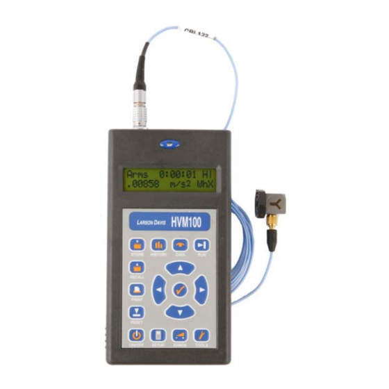
- Page 15 10-32 Female 10-32 Male About the HVM100 The HVM100 is a powerful, all digital, vibration analyzer. It features simultaneous 3 channel measurements, small light- weight design, easy to read display, portability utilizing 2 AA batteries, 115.2 kbps RS-232 interface, three modes of...
-
Page 16: Modes Of Operation
Modes of Operation The HVM100 is divided into three modes of operation. The standard mode is the vibration mode. This is the mode included with the instrument. The other two modes are optional modes. -
Page 17: Band Limiting Filters
- 3 dB corner frequencies at the frequencies listed in table 3 below. When a frequency weighting is selected in the HVM100 Hand-Arm mode, or Whole Body mode, the HVM100 automatically places both the weighting filter and the appropriate band-limiting filter in the signal path. - Page 18 1-10 HVM100 User Manual 4/11/03...
-
Page 19: Chapter 2 Getting Started
This section will introduce you to the keypad and functional- ity of the HVM100. Menu Navigation Navigating through the HVM100”s menus is similar to navi- gating through other Larson Davis instruments. The menus are arranged in lists. The appropriate menu key is used to enter the menu, and then the u Up and d Down arrow keys are used to scroll through the menu. - Page 20 Step 2 Press the c key to place the HVM100 into the modify mode. The selection will begin to blink. H e a d e r 1 Step 3 Use the r and l arrow keys to select a posi- tion to modify.
-
Page 21: Indexed Menu Function
O p e r a t i n g M o d e V i b r a t i o n Step 2 Press the c key to place the HVM100 in the mod- ify mode. The selection will begin to blink. -
Page 22: Key Board Functions
W h o l e B o d y Key Board Functions The keyboard on the front of the HVM100 is the main inter- face to the instrument. The keyboard consists of 11 dedi- cated function keys, 4 arrow keys and the check key. -
Page 23: Setup Key
Setup Key The SETUP key places you into the Setup menu. This menu is used to set general system parameters such as operating mode and frequency weighting. The selections available in the Setup menu are described below. The Setup menu is a circular menu. -
Page 24: Averaging Time
The only selections are Slow, 1 sec, 2 sec, 5 sec, 10 sec, 20 sec, 30 exponential detector in the HVM100 is sec, and 60 sec. The Slow response is a 1 second exponential the Slow detector. This detector will detector, while the others are linear repeat type averages. -
Page 25: Store Time
SETUP key and then use the u and d arrow keys to navigate through the menu items. The Auto Store function in the HVM100 will allow you to NOTE: The data memory in the HVM100 is a non-volatile EEPROM chip. Even if store data over time. -
Page 26: 2Nd History
Time History buffer. The Peak will be stored for all three channels and the Sum channel. Turning on the 2nd value will cut the number of sample storage space from 240 sam- ples to 120 samples. HVM100 User Manual 4/11/03... -
Page 27: Vibration Mode Weighting
In the 2nd history selection menu you have the choice of NOTE: To view each selection, first press the c key, and then press the r or l None or Peak. arrow key to scroll through each selec- 2 n d h i s t o r y tion. -
Page 28: Whole Body Weighting Mode
W e i g h t i n g X W e i g h t i n g X NOTE: The Wg frequency weighting curve is defined in BS 6841:1987. W e i g h t i n g X 2-10 HVM100 User Manual 4/11/03... - Page 29 W e i g h t i n g X 4/11/03 Getting Started 2-11...
- Page 30 2-12 HVM100 User Manual 4/11/03...
-
Page 31: Tools Menu
C H A P T E R Tools Menu The Tools menu has settings relating to the transducer and setup information relevant to the instrument. Selections include communications, printing, headers, etc. Tools Key The tools menu functions in exactly the same manner as the Setup menu and has the following selections: Accelerometer Hint:... -
Page 32: Display Units
NOTE: To view each selection, first press the c key, and then press the r or l printed by the HVM100. The HVM100 can display data in arrow key to scroll through each selec- six different formats. The selection of the display units will tion. -
Page 33: Integration
The choices are: m/s , cm/s ft/s , in/s , g, and dB. NOTE: The HVM100 uses a reference acceleration of 10 (velocity refer- D i s p l a y U n i t s ence = 10... -
Page 34: Sum Factor X,Y, Z
In the process of calculating the sum quantities (the data that appears under the ∑ menu) the HVM100 multiplies the instantaneous acceleration for each channel by a scaler fac- tor (sometimes called a k-factor). The HVM100 allows the user to select a different k factor for each channel. - Page 35 The AC/DC outputs on the HVM100 are independent and simultaneous for all three channels. First we will discuss the output in general, and then give the specific settings for the AC/DC outputs. AC output is useful for frequency analysis by an external...
- Page 36 The AC output will produce a signal from 0 - 0.5 Volt RMS. The scale of the DC output is typically 5 mV/dB. The level Typically varies between 0 Vdc to +1.0 Vdc. HVM100 User Manual 4/11/03...
-
Page 37: Ac/Dc Output Settings
A C / D C O u t p u t X proportional to the RMS sum level displayed ∑ on the HVM100. D C : r m s DC: min ∑ This signal will be a DC voltage with a level... -
Page 38: Baud Rate
It is important that the setting on your computer or on the NOTE: To view each selection, first press the c key, and then press the r or l serial printer match the Baud Rate setting of the HVM100. arrow key to scroll through each selec- tion. -
Page 39: Print History Selection
This allows you to clear the measurement files from the memory of the HVM100. The memory in the HVM100 is a non-volatile memory. If the batteries go dead, the measure- ment files will not be lost. The only way to clear out the file registers is to use the Erase All files menu. -
Page 40: Erase Setups
TOOLS key and then use the u and d arrow keys to navigate through the menu items. The HVM100 has the ability to store 10 setups internally in the memory. This is accomplished, as explained later in the manual, by pressing the STORE key while in the setup menu. -
Page 41: Header 1,2,3
TOOLS key and then use the u and d arrow keys to navigate through the menu items. The HVM100 has 3 Heading information screens. This will allow you to enter descriptive information into the instru- ment, that will then be printed out with the reports. The information can be up to 16 characters in length in each screen. - Page 42 Step 2 You will have either a blank screen, or a screen the HVM100 to accept the entry. that has previously entered information. H e a d e r 1...
-
Page 43: Language
TOOLS key and then use the u and d arrow keys to navigate through the menu items. The HVM100 has the ability to display and print in several NOTE: To view each selection, first press the c key, and then press the r or l different languages. - Page 44 3-14 HVM100 User Manual 4/11/03...
-
Page 45: Range Menu
HVM100 will use its Auto-Range algorithm to adjust the gain for all three channels such that the steady state input signal can be properly measured by the HVM100. (The gain is adjusted so that the signal falls within the top 20 dB of the HVM100’s analog to digital converter’s range.) -
Page 46: Gain X, Y, Z
The selections for the gain will be either 0, 20, 40, or 60 dB. Once the gain selection is stable, press the c key to save the settings. The HVM100 must be stopped and reset before the Auto-Range function can be used. -
Page 47: Cal Level
NOTE: To change the Cal Level parame- ter, press the c key, use the u and d set so that the level of the calibrator is within the HVM100’s measurement range. For example, when using a 1.0 g rms arrows to select the desired value, and... -
Page 48: Sensitivity X, Y, Z
Step 3 Start the calibrator. Step 4 Press the c key on the HVM100. The screen will start to flash values. When the level of your cali- brator appears in the screen, and the reading is sta- ble, press the c key again. -
Page 49: Reference Acceleration
RANGE key and then use the u and d arrow keys to navigate through the menu items. The HVM100 uses the following reference values to display NOTE: To view each selection, first press the c key, and then press the r or l... - Page 50 HVM100 User Manual 4/11/03...
-
Page 51: Chapter 5 Printing
Input Connector Serial Port External Power Only the current data in the HVM100 can be printed. To NOTE: The print key only works if you are currently in the History or Data print a stored data file, first recall the data file from memory menu. -
Page 52: Printer Cables
Printing to a Printer Printing to a printer is the easiest way to download data from the HVM100. The printer must have a serial interface. Some desktop laser printers will have a serial port on the back, or serial port option available. There are also some portable printers available that have a serial port. -
Page 53: Printing To A Windows Hyperterminal
Step 2 Use the Print History setting (located in the Tools menu), to select whether or not to include Time History data in the printed report. Step 3 Connect CBL006 to the I/O port on the HVM100, and to the communications port on your computer. 4/11/03... - Page 54 Step 4 Locate Hyperterminal on your computer. Hyper- terminal is usually found in the Start menu, under Programs, and in the Accessories folder. HVM100 User Manual 4/11/03...
- Page 55 Step 5 Select Hyperterminal from the menu. A new con- nection dialog box will appear. 4/11/03 Printing...
- Page 56 Step 6 Enter a name, and choose an icon for your Hyper- terminal connection. HVM100 User Manual 4/11/03...
- Page 57 Step 7 Press the OK button. 4/11/03 Printing...
- Page 58 Step 8 The Connect to dialog box will appear. HVM100 User Manual 4/11/03...
- Page 59 Step 9 The last selection in this box is the ‘Connect using’ selection box. This will allow you to select the Com port you will use to communicate with the HVM100. Select the Com port you plugged your HVM100 into. Press OK. 4/11/03...
- Page 60 Step 10 The Communications properties screen will appear. Select the Baud rate (bits per second) that matches the baud rate on your HVM100. The other settings are: • Data bits: 8 • Parity: None • Stop Bits: 1 • Flow Control: Hardware...
- Page 61 Step 11 Press the OK button. You have now established a connection for the HVM100. You will notice that in the lower left corner of the Hyperterminal screen it states that there is a connection, and will show how long the connection has been in place.
- Page 62 Left click the Properties button Properties Settings 5-12 HVM100 User Manual 4/11/03...
- Page 63 Left click the Settings Tab at the top of the window to open the Setting dialog box. 4/11/03 Printing 5-13...
- Page 64 Configure the items as shown above and press OK to close the ASCII dialog box.. Press OK to close the Properties window. Left click Transfer box which will open the following dialog box.. Highlight Capture Text and left click. 5-14 HVM100 User Manual 4/11/03...
- Page 65 This will open the following menu Use the Browse function to identify the file into which you want the data transfered and press Start. After the connection has been established, press the PRINT key on the HVM100 4/11/03 Printing 5-15...
- Page 66 Left click Transfer, highlight Stop on the drop-down menu and left click. The data can now be found as a Test file in the folder designated for saving the transfered file. 5-16 HVM100 User Manual 4/11/03...
- Page 67 4/11/03 Printing 5-17...
- Page 68 5-18 HVM100 User Manual 4/11/03...
-
Page 69: Chapter 6 Storing And Recalling Data Files And Setups
HVM100’s internal memory. STORE Key The STORE key on the HVM100 has two functions. It will allow you to store data files, and setups. The functionality is determined by the menu you are currently viewing. If you press the store key while you are viewing the Data or His- tory menu, you will be prompted to store a file. - Page 70 Erase Setups S t o r e S e t u p selection. Press the c key, use the r arrow key to change the selection to Yes, and press the c key again. HVM100 User Manual 4/11/03...
- Page 71 Step 5 Press the l arrow key to scroll to the naming section of the screen. You can now enter a name for the setup. Use the u and d arrows to select characters for the positions and the r and l arrow keys to move to the different positions.
-
Page 72: Storing A File
S t o r e F i l e Step 4 Use the u and d arrow keys to select the desired file register. S t o r e F i l e HVM100 User Manual 4/11/03... -
Page 73: Temporary Data Storage - File Register 00
File register 00 is normally used as a temporary data storage location. For example, if there is un-stored data in the HVM100 and the off key is pressed, the following screen will appear. S t o r e F i l e N o ^ A b o r t Y e s Select “No”... -
Page 74: Data Storage - File Registers 01 Thru 99
10 files in file registers 01 thru 10. Then, you turn off the HVM100. When the HVM100 is turned on again, if you try to store data, the HVM100 will prompt you to store data in file register 11, which is the next empty file register (see screen below). -
Page 75: Recall Key
Recall Key In order to use a setup, or to print a stored file they must be recalled into the current memory of the HVM100. The RECALL key is again dependent on the menu being viewed when the key is pressed. If you are in the Tools, Setup or Range menu and press the RECALL key, you will be prompted to recall a setup. - Page 76 Step 1 Enter one of the three valid menus for recalling a setup. The Range menu, the Setup menu, or the Tools menu. HVM100 User Manual 4/11/03...
- Page 77 Step 2 Press the RECALL key. Step 3 You will now be prompted to recall a setup. R e c a l l S e t u p Step 4 Use the u and d arrow keys to scroll through the setups until the desired setup appears on the screen.
-
Page 78: Recalling Setup Register S0 At Power-On
S0, and the HVM100 will automatically recall that setup every time the HVM100 is turned on. If for some reason, the HVM100 needs to be reset to its orig- inal factory default settings, the user can erase all setup reg- isters (see chapter 3, Tools Menu). - Page 79 Step 2 Press the RECALL Key on the HVM100. Step 3 The screen will prompt you to recall a file. R e c a l l F i l e Step 4 Use the u and d arrow keys to move to the desired selection.
- Page 80 6-12 HVM100 User Manual 4/11/03...
-
Page 81: Taking Measurements/Viewing Data On The Hvm100
Stop Indicator. Indicates that the HVM is not running. Latching Overload Indicator. Run - Interrupted Indicator Overload Detection When an overload occurs on the HVM100 the meter will perform three functions for the overloaded channel. 4/11/03 Taking Measurements/ Viewing Data on the HVM100... -
Page 82: Under-Range Indicator (?)
O v e r * F c X • The HVM100 uses an * to indicate that an overload has occurred since the last reset. The * is displayed on all channels regardless of which channel was overloaded. -
Page 83: History Key
1 . 5 0 0 0 m / s F a 2 History Key The HVM100 will store a time history based on the sample NOTE: To view each selection, first press the c key, and then press the r time selected. - Page 84 The HISTORY key works much the same as the other menus in the HVM100. To view the Time History data, press the HISTORY key. HVM100 User Manual 4/11/03...
- Page 85 . 0 1 9 0 0 m / s F a Z A r m s 0 : 0 0 : 0 1 . 0 1 9 0 0 m / s F a Z 4/11/03 Taking Measurements/ Viewing Data on the HVM100...
-
Page 86: Viewing Time History With 2Nd History Turned On
P e a k 0 : 0 0 : 0 1 4 . 3 8 0 0 m / s F a Z A r m s 0 : 0 0 : 0 1 1 . 5 0 0 0 m / s F a Z HVM100 User Manual 4/11/03... -
Page 87: Data Key
1, 2, 4, and 8 refer to A ( 2 ) . 0 0 0 7 3 F a Z the run time in Hours. (A (8) is the Energy Equivalent level projected over 8 hours) 4/11/03 Taking Measurements/ Viewing Data on the HVM100... - Page 88 Display Units are set to "g" or "dB", the VDV becomes an undefined quantity. Therefore, if the display units are "g" or "dB", the HVM100 will display a series of dashes (------) for the value. NOTE: The Short-Term Crest factor...
-
Page 89: Powering The Hvm100
C H A P T E R Powering the HVM100 Batteries The HVM100 operates on 2 AA batteries. See Appendix A for information on typical battery life. Checking the Remaining Battery Voltage The battery voltage can be viewed from the data menu by pressing the c key. - Page 90 Step 1 Remove battery cover from the side of the case. Step 2 Remove old batteries. HVM100 User Manual 4/11/03...
- Page 91 Step 3 Arrange new batteries according to diagram on the inside of the case. Make sure polarity of the batter- ies is correct. Step 4 Gently push the new batteries in the case while pushing the battery cover over the battery opening. 4/11/03 Powering the HVM100...
-
Page 92: Using External Power
Using External Power The HVM100 can also operate on 7 to 30 Volts DC external power. The external power connector is on the top of the HVM100. Input Connector Serial Port External Power The power supply normally used with the HVM100 is the Larson Davis PSA027. - Page 93 The connector pinout is as follows: Negative (-) Positive (+) Positive (+) Negative (-) 4/11/03 Powering the HVM100...
- Page 94 HVM100 User Manual 4/11/03...
-
Page 95: Connections On The Hvm100
C H A P T E R Connections on the HVM100 There are 4 connectors located on the outside case of the HVM100. The Serial Port, input connector, external power connector, and AD/DC Output connector. Input Connector Serial Port External Power Top connectors on HVM100. -
Page 96: Serial Interface Port
Serial Interface Port The serial port is used for communicating with the HVM100. The serial port also provides the printer connec- tion. Pinout The pinout is as follows, Pin Num- Description 1 - RTS Request To Send 2 - CTS... -
Page 97: Cables Used
The shell of the connector is connected to the Case Shield Ground Cables Used The standard cable used with the HVM100, is the CBL006. This is a serial connection cable and can be used when com- municating through software or printing to a Hyperterminal connection. -
Page 98: Transducer Connection
Transducer Connection The transducer connection is the input connection into the HVM100. It is located on the top of the HVM100 case. The connector used is a standard 4-pin LEMO™ connector. Pinout The pinout is a follows, Pin # Description... -
Page 99: External Power Connection
External Power Connection The HVM100 can also operate on 7 to 30 Volts DC external power. The external power connector is on the top of the HVM100. Pinout The connector pinout is as follows: Negative (-) Positive (+) Positive (+) -
Page 100: Ac/Dc Output Connector
DC output, with an averaging time of 60 seconds. The AC output will produce a signal from 0 - 0.5 Volt RMS. The scale of the DC output is typically 5 mV/dB. The level typically varies between 0 Vdc to +1.0 Vdc. HVM100 User Manual 4/11/03... -
Page 101: Pinout
The signal that is output on each pin is selectable for each channel. The selections are the same for each channel. We will list the X channel selections, however the available selections will be the same for all operating modes as well. 4/11/03 Connections on the HVM100... - Page 102 HVM100 User Manual 4/11/03...
-
Page 103: Appendix A Specifications
General Characteristics Type Precision The Larson Davis HVM100 Human Vibration Meter is a Type 1 instrument designed for use in assessing vibration as perceived by human beings. The instrument meets the requirements of ISO 8041:1990(E) including Ammendment 1: 1999(E). -
Page 104: Effects Of Temperature
When changing from one type of input (Direct/Charge/ ICP®) to another or when changing the instruments gain set- tings, allow 10 seconds of stabilization time prior to per- forming a new measurement. Data Storage • 1/2 Mega Byte Memory HVM100 User Manual 4/11/03... -
Page 105: Data Communications
• Capable of storing 100 files and 10 setups • 2 minute (typical) data retention for clock during battery change Data Communications • RS-232 Serial Interface • Maximum Data Rate: 115,000 bits per second Digital Display • 2 line, 32 digit, 7 segment LCD display •... -
Page 106: Declaration Of Conformity
Declaration of Conformity Larson Davis Inc. Declares that: • Product Name: Human Vibration Meter • Model: HVM100 in accordance with the following directives: • 89/336/EEC The Electromagnetic Compatibility Direc- tive and its amending directives has been designed and manufactured to the following speci- fications: •... -
Page 107: Direct Input
Direct Input Signal 50Ω Generator Ground ICP® Input Signal 50Ω 3300µF Generator 1.65 kΩ Ground Charge Input Signal 50Ω Generator 1000pF 1000pF 1000pF Ground 4/11/03 A -5... -
Page 108: Functions Measured
Reference Calibration Frequency Operating Mode Frequency Weighting Reference Calibration Frequency Vibration Fa (0.4 Hz to 100 Hz) 7.96 Hz Ws (Severity) 79.6 Hz Fb (0.4 Hz to 1250 Hz) Fc (6.3 Hz to 1250 Hz) HVM100 User Manual 4/11/03... -
Page 109: Reference Calibration Vibration
Operating Mode Frequency Weighting Reference Calibration Frequency Hand Arm 79.6 Hz Whole Body 7.96 Hz Reference Calibration Vibration The reference calibration vibration is 1 m/s Frequency Weighting Curves Fa (Flat 0.4 Hz to 100 Hz) Freq ( Hz) Freq ( Hz) Fa dB Tolerance Nominal... - Page 110 12.59 0.00 +1/-1 16.0 15.85 -0.01 +1/-1 20.0 19.95 -0.02 +1/-1 25.0 25.12 -0.04 +1/-1 31.5 31.62 -0.11 +1/-1 40.0 39.81 -0.27 +1/-1 50.0 50.12 -0.64 +1/-1 63.0 63.10 -1.46 +1/-1 80.0 79.43 -3.01 +1/-1 100.0 HVM100 User Manual 4/11/03...
-
Page 111: Fb (Flat 0.4 Hz To 1260 Hz) Frequency Weighting
Freq ( Hz) Freq ( Hz) Fa dB Tolerance Nominal True -5.46 +2/-2 125.9 -8.64 +2/-2 158.5 -∞ -12.27 199.5 -∞ -16.11 251.2 -∞ -20.04 316.2 -∞ -24.02 398.1 Fb (Flat 0.4 Hz to 1260 Hz) Frequency Weighting Freq ( Hz) Freq ( Hz) Fb dB Tolerance... - Page 112 0.00 +1 / -1 199.5 -0.01 +1 / -1 251.2 -0.02 +1 / -1 316.2 -0.04 +1 / -1 398.1 -0.11 +1 / -1 501.2 -0.27 +1 / -1 631.0 -0.64 +1 / -1 794.3 A-10 HVM100 User Manual 4/11/03...
-
Page 113: Fc (Flat 6.3 Hz To 1260 Hz), Wh, And Ws Frequency Weighting
Freq ( Hz) Freq ( Hz) Fb dB Tolerance Nominal True -1.46 +2 / -2 1000 1000 -3.01 +2 / -2 1250 1259 -5.46 +2 / -2 1600 1585 -8.64 +2 / -2 2000 1995 -∞ -12.27 +2 / 2500 2512 -∞... - Page 114 1000 1000 -3.01 -40.97 +2 / -2 -1.70 +4 / -4 1250 1259 -5.46 -45.42 +2 / -2 -4.30 +4 / -4 1600 1585 -8.64 -50.60 +2 / -2 -9.80 +4 / -4 2000 1995 A-12 HVM100 User Manual 4/11/03...
-
Page 115: Wb, Wc, And Wd Frequency Weightings
Freq ( Hz) Freq ( Hz) Fc dB Wh dB Tolerance Ws dB Tolerance Nominal True -∞ -12.27 -56.23 +2 / -16.30 +4 / -4 2500 2512 -∞ -16.11 -62.07 +2 / -25.80 +4 / -4 3150 3162 -∞ -20.04 -68.01 +2 / -36.00... - Page 116 -28.56 -34.57 -46.62 +2 / -2 158.5 -∞ -34.03 -40.20 -52.24 +2 / 199.5 -∞ -39.69 -46.04 -58.09 +2 / 251.2 -∞ -45.65 -51.98 -64.02 +2 / 316.2 -∞ -51.84 -57.95 -70.00 +2 / 398.1 A-14 HVM100 User Manual 4/11/03...
-
Page 117: We,Wj, And Wk Frequency Weighting
We,Wj, and Wk Frequency Weighting We dB Wj dB Wk dB Freq ( Hz) Freq ( Hz) Tolerance Nominal True -∞ -24.08 -30.18 -30.11 +2 / 0.100 0.100 -∞ -20.09 -26.20 -26.14 +2 / 0.125 0.1259 -∞ -16.14 -22.27 -22.21 +2 / 0.160 0.1585... -
Page 118: Wg Frequency Weighting (Defined In Bs6841:1987
+1 / -1 1.25 1.26 -4.6 +1 / -1 1.60 1.59 -3.4 +1 / -1 2.00 2.00 -2.2 +1 / -1 2.50 2.51 -0.9 +1 / -1 3.15 3.16 -0.0 +1 / -1 4.00 3.98 A-16 HVM100 User Manual 4/11/03... -
Page 119: Wb (Whole Body) Frequency Weighting
Freq ( Hz) Freq ( Hz) Wg dB Tolerance Nominal True +0.4 +1 / -1 5.00 5.01 +0.1 +1 / -1 6.30 6.31 -1.0 8.00 7.94 -2.5 +1 / -1 10.0 10.00 -4.2 +1 / -1 12.5 12.59 -6.3 +1 / -1 16.0 15.85 -8.2... - Page 120 -15.09 +1 / -1 31.5 31.62 -17.10 +1 / -1 40.0 39.81 -19.23 +1 / -1 50.0 50.12 -21.58 +1 / -1 63.0 63.10 -24.38 +2 / -2 80.0 79.43 -27.93 +2 / -2 100.0 A-18 HVM100 User Manual 4/11/03...
-
Page 121: Vibration - Fa
Freq ( Hz) Freq ( Hz) WB dB Tolerance Nominal True -32.37 +2 / -2 125.9 -37.55 +2 / -2 158.5 -∞ -43.18 +2 / 199.5 -∞ -49.02 +2 / 251.2 -∞ -54.95 +2 / 316.2 -∞ -60.92 +2 / 398.1 -∞... -
Page 122: Vibration - Fb, Fc, Ws
1. Under-Range (?) - The noise floor is below the measure- ment range of the analog to digital converter. 2. The data in the above table was obtained by electrically testing the HVM100. Vibration - Fb, Fc, Ws Direct Charge (1000pF) ICP®... -
Page 123: Hand Arm - Wh
45-77 20-74 45-77 Notes: 1. Under-Range (?) - The noise floor is below the measure- ment range of the analog to digital converter. 2. The data in the above table was obtained by electrically testing the HVM100. 4/11/03 A -21... -
Page 124: Whole Body - Wb
49-77 Notes: 1. Under-Range (?) - The noise floor is below the measure- ment range of the analog to digital converter. 2. The data in the above table was obtained by electrically testing the HVM100. A-22 HVM100 User Manual 4/11/03... -
Page 125: Whole Body - Wc
48-77 33-74 58-77 Notes: 1. Under-Range (?) - The noise floor is below the measure- ment range of the analog to digital converter. 2. The data in the above table was obtained by electrically testing the HVM100. 4/11/03 A -23... -
Page 126: Whole Body - Wd, We
58-77 Notes: 1. Under-Range (?) - The noise floor is below the measure- ment range of the analog to digital converter. 2. The data in the above table was obtained by electrically testing the HVM100. A-24 HVM100 User Manual 4/11/03... -
Page 127: Whole Body - Wg
49-77 24-74 49-77 Notes: 1. Under-Range (?) - The noise floor is below the measure- ment range of the analog to digital converter. 2. The data in the above table was obtained by electrically testing the HVM100. 4/11/03 A -25... -
Page 128: Whole Body - Wb, Wj, Wk
53-77 Notes: 1. Under-Range (?) - The noise floor is below the measure- ment range of the analog to digital converter. 2. The data in the above table was obtained by electrically testing the HVM100. A-26 HVM100 User Manual 4/11/03... -
Page 129: Appendix B Glossary
A P P E N D I X Glossary The following appendix contains definitions and explana- tions of terminology used in the HVM100 Table of equations The following table gives many of the calculations the HVM performs to arrive at the results reported by the instrument. -
Page 130: Allowed Exposure Time
Description Equation Allowed ⁄ ⁄ × Exposure Time 2.8m s 8hours Energy The HVM100 measures the following quantities: Equivalent RMS Acceleration ∫ A 8 ( ) t ( ) t d ------------------- a 8Hours ∫ A 4 ( ) t ( ) t d... -
Page 131: Running Rms Acceleration Exponential
Description Equation Running RMS Acceleration EXPONENTIAL ∫ t ( ) -- - a ----- - Arms τ τ ∞ τ = Time constant of the measurement. An averaging time of SLOW is equivalent to a time constant of 1 second. Vibration Dose Value -- -... -
Page 132: Short Term Maximum Peak
(t) = X, Y, and Z axis instantaneous acceleration = X, Y, and Z axis Sum Factors The HVM100 uses the formula above to calculate the instantaneous, summed acceleration, a (t). This value is then used to calculate a sum w∑... -
Page 133: Appendix C Serial Interface Commands
Mode specific parameter selections can vary based on the selected operating mode. Setup commands can be sent at any time. If the HVM100 is running, and changing the parameter requires a reset, then the setup command will cause the instrument to automati- cally stop, reset, change the parameter setting and start run- ning again. -
Page 134: Syntax For Query Commands
For indexed parameters (i.e. parameters for which there is a specific set of choices) the HVM100 returns the index number (i.e. 0, 1, 2, etc.). For alphanumeric parameters the HVM100 returns an ASCII string. -
Page 135: Mode Specific Parameters
0 = 2400 1 = 9600 2 = 38.4k 3 = 115.2k NOTE: The baud rate change takes effect immediately after the “OK” response from the HVM100 Mode Specific Parameters The following parameters are dependent on which operating mode is selected: Command... - Page 136 = 0 to 2 i = 0 to 2 0 = Direct 0 = Direct 0 = Direct 1 = ICP 1 = ICP 1 = ICP 2 = Charge 2 = Charge 2 = Charge HVM100 User Manual 4/11/03...
- Page 137 Command Parameter Vibration Hand Arm Whole Body S31, i Display Units i = 0 to 5 i = 0 to 5 i = 0 to 5 0 = m/s 0 = m/s 0 = m/s 1 = cm/s 1 = cm/s 1 = cm/s 2 = ft/s 2 = ft/s...
- Page 138 ∑ 7 = DC: min ∑ 8 = DC: max ∑ 8 = DC: max ∑ 8 = DC: max ∑ ∑ ∑ ∑ 9 = DC: peak 9 = DC: peak 9 = DC: peak HVM100 User Manual 4/11/03...
- Page 139 Command Parameter Vibration Hand Arm Whole Body S41, i AC/DC Output i = 0 to 9 i = 0 to 9 i = 0 to 9 AC: Weighted AC: Weighted AC: Weighted AC: Bandlimit AC: Bandlimit AC: Bandlimit 2 = DC: rms 2 = DC: rms 2 = DC: rms 3 = DC: min...
- Page 140 = 0 to 1 i = 0 to 1 i = 0 to 1 0 = 1e-05 m/s^2 0 = 1e-05 m/s^2 0 = 1e-05 m/s^2 1 = 1e-06 m/s^2 1 = 1e-06 m/s^2 1 = 1e-06 m/s^2 HVM100 User Manual 4/11/03...
-
Page 141: Read Data Commands
Not to be confused with Rx1, Ry1, Rz1 or Rs1. Hint: The HVM100 always returns data in decibels, referenced to (10 R Command nn Vibration Hand Arm Whole Body... -
Page 142: Read Time History Commands
Peak). The commands listed in the following table are also available. The date information (H0 - H5) refers to the starting date/time of the first history record. Hint: The HVM100 always returns data in decibels, referenced to (10 Command Parameter Settings... -
Page 143: Control Commands
HVM100 returns “OK” for valid command. Reset HVM100 returns “OK” for valid command. M4, n Store Setup HVM100 will store the current setup in the setup register n = 0 to 9 indicated by n (0 is default). Returns “OK” for valid com- mand. 4/11/03... - Page 144 Returns “NO” if a setup has never been stored in the nth setup location. M6, n Store File HVM100 will store a file in the location specified by n (0 is n = 0 to 99 default). Returns “OK” for valid command. M7, n Recall File HVM100 will recall the file specified by n (0 is default).
-
Page 145: Appendix D Frequency Response Curves
A P P E N D I X Frequency Response Curves The following are typical frequency response curves for the HVM100. Specifications are subject to change without notice. Numerical values given are typical. Refer to specific calibration or test results for accurate data on a specific unit. - Page 146 HVM100 User Manual 4/11/03...
- Page 147 4/11/03 D -3...
- Page 148 HVM100 User Manual 4/11/03...
- Page 149 4/11/03 D -5...
- Page 150 HVM100 User Manual 4/11/03...
- Page 151 4/11/03 D -7...
- Page 152 HVM100 User Manual 4/11/03...
- Page 153 4/11/03 D -9...
- Page 154 D-10 HVM100 User Manual 4/11/03...
- Page 155 4/11/03 D -11...
- Page 156 D-12 HVM100 User Manual 4/11/03...
- Page 157 4/11/03 D -13...
- Page 158 D-14 HVM100 User Manual 4/11/03...
-
Page 159: Appendix E Miscellaneous Information
DC output sensitivity should be calibrated, or measured, before it is used. Follow these steps to measure the DC out- put sensitivity. Step 1 Calibrate the HVM100 for the accelerometer that will be used. Step 2 Setup the HVM100 with the following settings: a. - Page 160 40 dB 20 dB Step 4 Connect a DC rms voltmeter to the DC output. Step 5 Turn on the calibrator and start the HVM100 run- ning. The HVM100 should display an Arms level of 1 g. Step 6 Note the voltage reading on the voltmeter. The voltage corresponds to 1 g rms of acceleration.
-
Page 161: Ac/Dc Outputs
DC Output For all of the Analog AC and Analog DC outputs, the output impedance of the HVM100 is 475 ohms. For minimal error, connect to instruments with an input impedance of greater than 100,000 ohms when making AC or DC output measure- ments. -
Page 162: Ac Output
20 dB). Therefore, in order for the HVM100’s AC output to function properly with each range (i.e. gain settings of 0, 20, 40, and 60 dB), the HVM100’s gain set- tings also affect the AC output signals. For example, with a gain setting of 0 dB, the HVM100 can measure input signals as large as 5.0 Vrms. -
Page 163: Typical Measurement Ranges For Hand-Arm And Whole Body Measurements
Typical Measurement Ranges for Hand-Arm and Whole Body Measurements ICP Accelerometers Hand-Arm (Wh) and Whole Body (WB, Wc, Wd, We, Wb, Wf, Wk) 1 mV/g 10 mV/g 100 mV/g Gain Peak Peak Peak Range Range Range Range Range Range 0 dB 5-5000 90-7000 0.5-500... - Page 164 0.005-0.07 Notes 1. The data in the above tables was calculated using the dBuV range data in the HVM100 User Manual. 2. The data in the above table was obtained by electrically testing the HVM100. 3. The data is based on ideal accelerometers (the noise floor and upper limit of the accelerometer were not consid- ered).
-
Page 165: Typical Measurement Ranges For General Purpose Vibration Measurements
Typical Measurement Ranges for General Purpose Vibration Measurements ICP Accelerometers Fa, Fb, Fc, Ws Weighting 1 mV/g 10 mV/g 100 mV/g Gain Peak Peak Peak Range Range Range Range Range Range 0 dB 5-5000 90-7000 0.5-500 9-700 0.05-50 0.9-70 20 dB 0.5-500 9-700 0.05-50... - Page 166 Notes 1. The data in the above tables was calculated using the dBuV range data in the HVM100 User Manual. 2. The data in the above table was obtained by electrically testing the HVM100. 3. The data is based on ideal accelerometers (the noise floor and upper limit of the accelerometer were not consid- ered).
-
Page 167: Appendix F Warranty/Customer Satisfaction
A P P E N D I X Warranty/Customer Satisfaction A. Total Customer Satisfaction. Larson Davis, Inc. ("LD") guarantees Total Customer Satisfaction. If, at any time you are not completely satisfied with any LD product, LD will repair, replace or exchange it at no charge, except as otherwise provided in this Limited Warranty. - Page 168 E. NO SPECIAL, INCIDENTAL OR CONSEQUENTIAL DAMAGES. LD'S SOLE OBLIGATIONS UNDER THIS LIMITED WARRANTY ARE SET FORTH ABOVE IN PARAGRAPHS A, B, C AND D. IN NO EVENT SHALL LD (ITS CONTRACTORS OR SUPPLIERS) BE LIABLE TO THE BUYER FOR ANY LOST PROFITS, DIRECT, INDIRECT, SPECIAL, INCIDENTAL OR CONSEQUENTIAL DAMAGES, WHETHER BASED ON CONTRACT, IN TORT OR ANY OTHER LEGAL THEORY.
- Page 169 2.DAMAGE CAUSED BY ACTS OF GOD THAT INCLUDE, BUT ARE NOT LIMITED TO, HAILSTORMS, WINDSTORMS, HURRICANES, TORNADOES, SANDSTORMS, LIGHTNING, FLOODS AND EARTHQUAKES. 3.DAMAGE UNDER CONDITIONS CAUSED BY FIRE OR ACCIDENT, BY ABUSE OR BY NEGLIGENCE OF THE USER OR ANY OTHER PERSON OTHER THAN LD, BY IMPROPER INSTALLATION, BY MISUSE, BY INCORRECT OPERATION, BY "NORMAL WEAR AND TEAR", BY IMPROPER ADJUSTMENT OR ALTERATION, BY ALTERATIONS NOT COMPLETED BY AUTHORIZED SERVICE PERSONNEL, OR BY...
- Page 170 Warranty/Customer Satisfaction April 11, 2003...
- Page 171 AC/DC Output Connector ...9-1 Frequency weighting Selections ..1-8 External Power ......9-1 Input Connector ......9-1 Serial Port ........9-1 Gain ............ 4-2 Connections on the HVM100 .....9-1 General Characteristics ...... A-1 Data Communications ......A-3 Hand Arm Data Key ..........7-7 Wh ..........1-8...
- Page 172 2nd History ........2-5 Overload Detection ......7-1 Auto Store ........2-5 Averaging Time ......2-5 Time History Settings ....2-5 Mode Selection ......2-5 Power Supply ........A-3 Store Time ........2-5 Powering the HVM100 .......8-1 Stabilization Time ......A-2 Print History ........3-9...
- Page 173 HVM100 User Manual Stop Key ..........7-1 Whole Body - Wd, We ....A-24 Store Key Whole Body - Wg ....... A-25 Storing a File .......6-4 Whole Body - Wj, Wk ....A-26 Storing a Setup ......6-1 Storing Data ........6-1 Storing Setups ........6-1 Under-Range indicator .......
- Page 174 HVM100 User Manual...
Need help?
Do you have a question about the HVM100 and is the answer not in the manual?
Questions and answers