Sign In
Upload
Download
Table of Contents
Contents
Add to my manuals
Delete from my manuals
Share
URL of this page:
HTML Link:
Bookmark this page
Add
Manual will be automatically added to "My Manuals"
Print this page
×
Bookmark added
×
Added to my manuals
Manuals
Brands
Larson Davis Manuals
Measuring Instruments
EPS044
Reference manual
Larson Davis EPS044 Reference Manual
Noise monitoring system
Hide thumbs
1
2
3
4
5
6
7
8
9
10
11
12
13
14
15
16
17
18
19
20
21
22
23
24
25
26
27
28
29
30
31
32
33
34
35
36
37
38
39
40
41
42
43
44
45
46
47
48
49
50
51
52
page
of
52
Go
/
52
Contents
Table of Contents
Bookmarks
Table of Contents
Table of Contents
Module 1
System Overview
Overview
EPS/NMS044 Features
Components
Optional Accessories
Wiring Diagrams
Module 2 Get Started
Overview
Ready Battery
Ready Battery
Charge Battery
Configure the RV50 Gateway
Install SIM Card
Configure for Remote Communication
Model 831C SLM Settings
Shutoff Voltage
Module 3 Deployment
Overview
Assemble EPS2116 and Preamplifier
Travel Packs
Install Pole and EPS2116 to System
Connect Solar Panel
Turn System on
Calibrate
Due Diligence
Verify Battery Is Charged/Charging
Check Cellular Service
Secure Case with Lock
Module 4 Making Measurements
Overview
Connect to G4 LD Utility
Default NMS044 Setup File
Email/Text Alerts
Appendix A Additional Features
Physical Characteristics
Long Term Storage
NMS044 Power Draw
Shipping Information
Sunlight Hours
Alternative Solar Panel
LED Indicators
Lithium Iron Phosphate Battery (Lifepo
Soundadvisor Model 831C Sound Level Meter
COM-RV50-DC-U/E Cellular Gateway
PSA038 Genasun Solar Charge Controller
Removing Cables from Case
Configuring LD Settings for the RV50
Declaration of Conformity
Advertisement
Quick Links
Download this manual
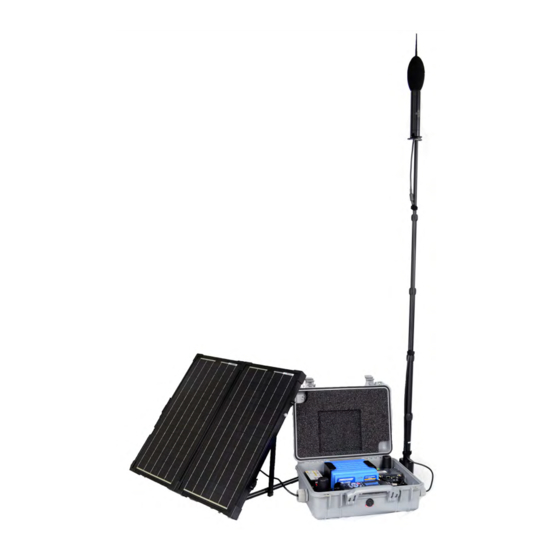
EPS044 & NMS044
Noise Monitoring System
Reference Manual
Table of
Contents
Previous
Page
Next
Page
1
2
3
4
5
Advertisement
Chapters
Table of Contents
5
Module 2 Get Started
14
Module 3 Deployment
22
Appendix A Additional Features
38
Table of Contents
Need help?
Do you have a question about the EPS044 and is the answer not in the manual?
Ask a question
Questions and answers
Subscribe to Our Youtube Channel
Related Manuals for Larson Davis EPS044
Measuring Instruments Larson Davis NMS044 Reference Manual
Noise monitoring system (52 pages)
Measuring Instruments Larson Davis 820 Technical Reference Manual
Sound level meter (193 pages)
Measuring Instruments Larson Davis System 824 Training Manual
Analyzer and precision sound level meter (143 pages)
Measuring Instruments Larson Davis SoundTrack LxT User Manual
(307 pages)
Measuring Instruments Larson Davis 824 Technical Reference Manual
Precision sound level meter & real time analyzer (673 pages)
Measuring Instruments Larson Davis 831 User Manual
Sound level meter (548 pages)
Measuring Instruments Larson Davis HVM200 Manual
Human vibration (88 pages)
Measuring Instruments Larson Davis System 824 Reference Manual
Sound level meter (536 pages)
Measuring Instruments Larson Davis SoundAdvisor 831C Reference Manual
Sound level meter (218 pages)
Measuring Instruments Larson Davis SoundTrack LxT N/Forcer Field Operation Manual
(12 pages)
Measuring Instruments Larson Davis HVM100 Manual
Human vibration meter (177 pages)
Measuring Instruments Larson Davis NoiseTutor User Manual
(100 pages)
Measuring Instruments Larson Davis Spartan 730 Reference Manual
Noise dosimeter (98 pages)
Measuring Instruments Larson Davis HVM200 Reference Manual
(77 pages)
Measuring Instruments Larson Davis SoundAdvisor NMS045 Reference Manual
Permanent noise monitoring system (64 pages)
Measuring Instruments Larson Davis Spartan 730 Reference Manual
Noise dosimeter (99 pages)
This manual is also suitable for:
Nms044
Table of Contents
Print
Rename the bookmark
Delete bookmark?
Delete from my manuals?
Login
Sign In
OR
Sign in with Facebook
Sign in with Google
Upload manual
Upload from disk
Upload from URL


Need help?
Do you have a question about the EPS044 and is the answer not in the manual?
Questions and answers