Table of Contents
Advertisement
Quick Links
Download this manual
See also:
Quick User Manual
Advertisement
Table of Contents

Related Manuals for Larson Davis 820


Summary of Contents for Larson Davis 820
- Page 1 Model 820 Sound Level Meter Technical Reference Manual...
- Page 2 Model 820 Technical Reference Manual Larson Davis, a division of PCB Piezotronics, Inc. 1681 West 820 North Provo, UT 84601-1341 24 Hour Hotline: (716) 926-8243 Toll Free (US): (888) 258-3222 www.larsondavis.com I820.01 Rev.D...
-
Page 3: Customer Service
Copyright Copyright 2009 by PCB Piezotronics, Inc. This manual is copyrighted, with all rights reserved. The manual may not be copied in whole or in part for any use without prior written consent of PCB Piezotronics, Inc. Disclaimer The following paragraph does not apply in any state or country where such statements are not agreeable with local law: Even though PCB Piezotronics, Inc. - Page 4 Purchase Date: _________________________ Recycling Larson Davis, Inc. is an environmentally friendly organization and encourages our customers to be environmentally conscious. When this product reaches its end of life, please recycle the product through a local recycling center or return the product to: Larson Davis, Inc.
-
Page 5: Table Of Contents
Unpacking and Inspection................1-12 Accessories.......................1-12 Optional Equipment ..................1-13 Battery Installation ...................1-17 Environmental Considerations .................1-18 Preparing to Use the Model 820 - Connecting the Mic/Preamp ......1-18 Chapter 2 Overview to Model 820 Understanding the Model 820 Keypad ..............2-1 Getting to Know Screen Symbols................2-8 Understanding the Model 820 Screen..............2-9... - Page 6 Changing Parameters — Enter, Modify.............8-3 Error Messages....................8-4 Learning to Store and Retrieve Setup Memory ............8-4 Storing a Setup ....................8-5 Recalling a Setup ....................8-6 Model 820 Setup Parameters ..................8-7 System (1-20) R U S ................8-7 Timer (21-27) U T....................8-10 Lock (28-34) U L .....................8-10 Calibration (35-38) U C ...................8-11...
- Page 7 Ln Statistical Levels (55-60) B ................8-13 Exceedance Levels (61-65) V ................8-14 Exceedance History (66-70, 161-163) .............8-14 Interval History (72-79) M Time History (80-87) ...................H8-15 Print Options (89-112) s...................8-18 Additional System Functions (152, 154-161) ..........8-19 Chapter 9 Memory Usage Determine Storable Data..................9-1 Estimating Memory Usage ..................9-3 Chapter 10 Printing a Report 10-1...
- Page 8 Data Communications..................A-10 Digital Display .....................A-10 Digital Display Resolution...................A-10 Display Bargraph ....................A-10 Real-time Clock/Calendar..................A-10 Run-time Clock....................A-11 Standards Met ......................A-11 CE Information ....................A-11 Power Supply .......................A-12 Dimensions/Weight (with Microphone, Preamplifier and Battery).....A-12 Appendix B Serial Port Interface Remote Control Model INT002 Interface Cable ................. B-2 Daisy Chain Addressing..................
- Page 9 Print Commands....................B-31 Error Messages and Warnings ................ B-32 Modem Control Mode ..................B-34 Modem Mode (154) ................... B-34 Dial Out Mode (155) .................. B-34 Monitor Number..................B-34 820 Phone Dialing Procedure..............B-35 Model 820 Answering Procedure............... B-35 Appendix C Glossary...
-
Page 10: Chapter 1 Introduction
The Model 820 measures sound with the ease of operation of a “point and shoot” sound level meter. The latest advances in surface mount technology, air condenser microphones, and internal firmware have been combined in a rugged, lightweight yet extremely versatile unit. - Page 11 Appendix A - Specifications: A listing of acoustic, elec- tronic, environmental, and physical characteristics of the Model 820. • Appendix B - Model 820 Serial Port Interface Remote Con- trol: Setting interface commands with their syntax. • Appendix C - Glossary: Definitions of key terms and con- cepts used in this manual.
-
Page 12: About This Chapter
Formatting Conventions This manual uses the following formatting conventions: Functions accessed by pressing a key on the Model 820 keypad are shown with an icon, for example: Press e and then press c. - Page 13 Step 1 Check the microphone polarization. To do this turn The flashing (f), the Keyboard Sta- on the Model 820, press R, m, 4 and 3, and tus Indicator, displays which key e. The following display will appear: functions are active. This indicates...
-
Page 14: Features
Especially important information is shown in italics, for example: To access items 48-50, Overall Exchange Rate, Overall Threshold, Overall Criterion, press the d key. Features The Larson Davis Model 820 meets the requirements of the American National Standards Institute (ANSI) S1.4,... - Page 15 • Battery level indication. • Standard 9V internal alkaline battery life of more than 16 hours (or external power using Larson Davis cable # CBL035 for longer measurements). • RS-232 computer and modem interface standard. All func- tions fully programmable. Comes complete with PC SWW_SLM_UTIL software for data retrieval and translate binary files to ASCII format.
-
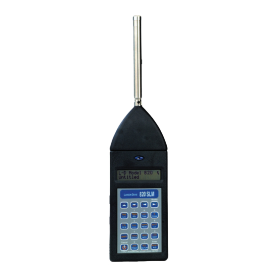
Page 16: Model 820 Components
Model 820 Components A layout of the Model 820 is shown below Microphone Microphone Preamplifier LCD Display Keypad 820 SLM ARSON AVIS Modify Connector AC/ TIME TIMER T.A. DOSE DC Out UWPK BATT PEAK Connector LOCK SHIFT EXCD INTV HIST... - Page 17 As can be seen, the standard Model 820 includes the following: • Model PRM828 is a 5 1/2 inch precision preamplifier using a standard 5 pin SwitchCraft™ connector and may be extended up to 20 feet with EXCXXX microphone cable. The preamplifier is removed by depressing the small black latch button with a fingertip, while gently pulling it away from the mating connector.
- Page 18 Please use a windscreen whenever possible. • A 20-key membrane keypad. • Model 820 precision hand-held Sound Level Meter with integral nose cone. Powered internally by 9 volt cell, or by an external battery or AC/DC adapter. • WS001 3 1/2 inch windscreen.
-
Page 19: Block Diagram
The Model 820’s large data memory relieves the user from the concern of data loss caused by memory limitations. Furthermore, measurements can be printed or transmitted at up to 19.2 K baud via RS-232 for further manipulation or... -
Page 20: Getting Started
The block diagram above shows how the Model 820 sound level meter merges state-of-the-art analog circuitry, a powerful microcomputer controller and a large amount of usable data memory. The signal from the precision air condenser microphone/ preamplifier is input directly to the linear peak detector and, through the selected A- or C-weighting filter, to the root- mean-square (rms) and weighted peak detectors. -
Page 21: Unpacking And Inspection
Preparing to use the Model 820 • Connecting the Microphone to the Preamp. You will then be ready to use the Model 820 for actual measurements (as described later in Chapter 4 of this manual). Unpacking and Inspection Your Model 820 has been shipped in protective packaging. -
Page 22: Optional Equipment
CBL040: Similar to INT002 but allows one to “daisy chain” an additional Model 820. • CBL042 AC/DC output of the Model 820 to RCA/BNC connectors. • CBL116 Connects Model 820 to a PC or a modem. Pro- Model 820 Technical Reference Manual Getting Started 1-13... - Page 23 Features lock hasp and may be chained through handle for security. • EPS013: Same as EPS012 but with 8 Ah, 12 Volt recharge- able battery BAT004. Provides 1 week operation in normal conditions. Includes CBL038 and battery charger. 1-14 Getting Started Model 820 Technical Reference Manual...
- Page 24 PSA002: AC/DC power adapter, 220 Vac to 9Vdc, 50-60 Hz for use with INT002. • 820-OPT01: Modification of the Model 820 for use in out- door noise monitoring system using the Model PRM2101 Outdoor Preamplifier. Includes addition of a second con- nection to the 820 for control of the electrostatic actuator.
- Page 25 PSA001 (alligator clips) CBL116 (1.5’) CBL077 (6’, optional) Laptop Computer PSA005 AC/DC Adaptor (2’) Battery CBL033 (6’) Serial Printer CBL116 (1.5’) CBL077 (6’, optional) (2’) Modem Battery Figure 1-4 820 System Diagram 1-16 Getting Started Model 820 Technical Reference Manual...
-
Page 26: Battery Installation
Battery Installation To insert the 9 volt battery in the Model 820, remove the battery cover at the lower left side of the instrument by sliding it out as shown in Figure 1-5 . Figure 1-5 Remove Battery With the battery door removed, drop the battery into the... -
Page 27: Environmental Considerations
For example, allow the Model 820 ample time to adjust to abrupt temperature changes. Condensation may form inside a cold Model 820 if it is brought into a warm room or vehicle and may persist long after the outside case has adjusted to the ambient temperature. -
Page 28: Overview To Model 820
Checking the Battery Voltage. • Turning off the Model 820. Understanding the Model 820 Keypad The keypad for the Model 820 has 20 keys as seen in the fol- lowing figure (Figure 2-1): Model 820 Technical Reference Manual Overview to Model 820... - Page 29 AVIS Modify TIME TIMER T.A. DOSE UWPK BATT PEAK LOCK SHIFT EXCD INTV HIST Cancel Enter RESET PRINT SETUP TYPE 1 INTEGRATING SOUND LEVEL METER Figure 2-1 Model 820 Keypad. Understanding the Model 820 Keypad Model 820 Technical Reference Manual...
- Page 30 ON: Turns on the Model 820. Cancel: When the Model 820 is on, this but- ton serves to return to a previous menu, or “Cancel” the present function.
- Page 31 #83-84. LOG: The Run/Stop Log is a time record of all the actions which start or stop the data tak- ing process of the Model 820. Understanding the Model 820 Keypad Model 820 Technical Reference Manual...
- Page 32 L is also uwpk shown. The number of times the weighted peak level exceeds a programmed threshold is also counted and displayed (-b window). Model 820 Technical Reference Manual Understanding the Model 820 Keypad...
- Page 33 BATT: This key gives the percentage of power remaining in the 9 V battery, or exter- nal supply. BATT-b: Gives Model 820 revision number and date. : The Equivalent Level or L is a Time Weighted Average based on an exchange rate of 3dB (true energy measure) with no thresh- old.
- Page 34 Modify: Prepares the field for changes while in setup. Model 820 Technical Reference Manual Understanding the Model 820 Keypad...
-
Page 35: Getting To Know Screen Symbols
Getting to Know Screen Symbols Symbols basic to the Model 820 are included below. These are generally found to the right of the screen. The Operating Mode Indicator, upper right character, indicates whether data is being accumulated or not and has the modes indicated by the first four examples. -
Page 36: Understanding The Model 820 Screen
Several characters are consistent in their appearance. We will now turn the Model 820 on and examine a variety of pos- sible screens. Turning On the Model 820... -
Page 37: Checking The Battery Voltage
At this point, you can change the parameters and begin taking actual measurements. Checking the Battery Voltage The Model 820 continuously monitors its battery voltage to Do not press the key during a ensure accurate measurements. It has a battery life of about measurement since it will pause sixteen hours. -
Page 38: Turning Off The Model 820
The second screen (b) gives revi- sion number and date. Turning Off the Model 820 To turn off the Model 820, simply press the UO key. The instrument will not allow itself to be turned off until in (Stop) mode. This feature will insure that no important data is lost. -
Page 39: Chapter 3 Calibration
However, you do not have to recalibrate the Model 820 when you change the settings. Please note that if you use a calibrator which uses another fre- quency some corrections may be required depending on the weighting. - Page 40 43. To do this turn on the Model 820, press R, m, 4 and 3, and e. The following display will appear: The flashing (f), the Keyboard Sta- tus Indicator, displays which key functions are active. This indicates...
- Page 41 Step 8 Press c to exit calibration setup. Then, acti- vate the calibrator by pressing the button on its side. Step 9 Press the on the Model 820. This Pressing the u will check cali- U and display indicates the current sensitivity off set and...
- Page 42 You may repeat the previous steps or perform a Cal check. Step 11 To Reset the Model 820 for re-calibration, press The display will ask if you want to U and R. “Reset ALL Data?” You do.
-
Page 43: Chapter 4 Quick Start
By using any white or Orange function keys Follow these steps to access the parameters using numeric val- ues: Step 1 With the Model 820 on, press R and the follow- ing screen appears: Model 820 Technical Reference Manual Quick Start... - Page 44 The third way to access Current Current Time. Notice the flashing (f) changes to (n). Time parameter, press Remember, press m to change or correct the field and press e. Setting Parameters Using Function Keys Model 820 Technical Reference Manual...
-
Page 45: Setting Parameters Using Numbers And Other Characters
Step 6 To exit the setup mode, press c. Setting Parameters Using Numbers and Other Characters The Model 820 has the ability to show 3 lines for your Com- pany Name and one line for the Measurement Title which is used on the reports. - Page 46 The number (3) appears in the lower right corner of the display indicating this panel is accessed. Figure 4-4 3 Shift Level - 3 Alpha-numeric Keyboard Setting Parameters Using Numbers and Other Characters Model 820 Technical Reference...
- Page 47 Step 1 To enter a name, for example, turn the Model 820 on All but the last of these screens you and press these keys to access the first name field: have seen before. This display is to set one of four custom instrument...
- Page 48 Step 9 The fourth line is for the Measurement Title. Press The first/fourth lines appear on thedkey. screen when the 820 is turned on. Setting Parameters Using Numbers and Other Characters Model 820 Technical Reference...
-
Page 49: Setting Time, Date, And Day Parameters
Setting Time, Date, and Day parameters Once you have set the parameters, you can now enter the cor- rect time and date. The Model 820 has a 24 hour (military time) clock where afternoon hours are denoted by adding 12 hours, e.g. -
Page 50: Ac/Dc Output
The AC output gives an AC signal proportional to input signal and can be Flat or A and C weighted. It is used to record input signal to the Model 820 (note Appendix A for more details). Figure 4-5 AC/DC Output Connector... -
Page 51: Chapter 5 Performing A Measurement/Reading The Data
The most basic function of the Model 820 is to measure sound pressure. Follow these steps to examine the SLM function key: Step 1 Turn the Model 820 on and wait for the unit to become stable. Press S. The stick figure in the... - Page 52 Note * * * * that even in the stop mode the Model 820 continues to monitor a. Parameter 61: RMS Exceedance. SPL while in this window. b. Parameter 62: RMS Exceedance 2.
- Page 53 Step 4 Press the d key again for the second screen: The Peak and Unweighted Peak are displayed here. Note that even in the stop mode, the Model 820 continues to display the detected values on the upper right hand side of the screen.
- Page 54 Step 1 To access these parameters turn the Model 820 on by Slow: exponential avg.: 1 second pressing c. Next press R m 3 9 constant.
-
Page 55: Lmax-Lmin
(A16, C16 and Flat do not apply to the Model 820). Step 4 The Model 820 has been preset at [A]. To change the setting press mr to the preferred setting and Step 5 Find item 41 by pressing d, AC Out Weighting, F+20 means Flat plus 20 dB of which has the values listed here. - Page 56 The current measurement L the following display will appear: occurred on November 27, 1996, at 9:21 A.M. (Remember, the Model 820 used military time to designate between A.M. and P.M.) That L value was 51.5 dB. There are no other screens avail- able from this display.
-
Page 57: Peak-Uwpk
PEAK-UWPK The Model 820 also has a peak level detector. Its values, dur- ing the measurement (or when stopped), are found by pressing the K key. Step 1 Access Peak values. Press K: PEAK is a weighted value and rep- resents a true Peak SPL from the on-board Peak Detector. - Page 58 Parameters 57-58 were set at the three: given values shown in the screen and their readings are apparent. Press the r key to see the third screen and the values recorded there. Taking a Measurement Model 820 Technical Reference Manual...
-
Page 59: Leq
(parameters 48-50) may not be modified once the measure- (or Criterion Time) applies to Cur- ment has started without a reset. However, OVERALL CRI- rent Overall and LDL. TERION may be changed at any time. Model 820 Technical Reference Manual Taking a Measurement... - Page 60 The Current Threshold, item 46, has a range from 0 to 255 dB. Step 2 Press the d key and choose the desired dB level for The normal Dose setting for the Current Threshold. Larson Davis has preset this threshold is 80 dB which allows parameter to 80 dB.
- Page 61 Criterion settings, press m, enter the desired val- ues, and press e. Step 9 To look at LDL, press U and E. This step will not work while in the SETUP mode either. Model 820 Technical Reference Manual Taking a Measurement 5-11...
- Page 62 3 dB (parameter 48). The Overall Criterion has been set at 90 (parameter 50). Any of these 3 parameters can be modified and a new dose, projected dose, Leq and SEL will be computed. 5-12 Taking a Measurement Model 820 Technical Reference Manual...
- Page 63 7:00 PM and 10:00 PM. Ex in the second screen takes all exceedance records and aver- ages them together. BkGnd is the overall Leq of all samples that were not an event. Model 820 Technical Reference Manual Taking a Measurement 5-13...
-
Page 64: Battery
Step 1 Press U and M. A screen similar to the fol- This screen shows the percentage lowing will appear: of memory left of the total avail- able. 248837 divided by 250793 = 99.21% 5-14 Taking a Measurement Model 820 Technical Reference Manual... -
Page 65: Stopping The Measurement
Press S to stop the measurement. The stick figure will return to the resting position. To view any of the previous mea- surement data simply press the appropriate key and the infor- mation will appear. Model 820 Technical Reference Manual Stopping the Measurement 5-15... -
Page 66: Chapter 6 Timed Measurement
Using the Timer for Unattended Readings. Examine the t capabilities by looking at the parameter fields: Step 1 Turn the Model 820 on, press O followed by R, The Timer parameters, 21-27 U, and t. The following display will begin with this screen, parameter... - Page 67 If the date is incorrect, simply 26 96. Press e. The new Timer Run Date press m and enter the correct is now 26 Sep 1996. data, then press e. Using the Timer for Unattended Readings. Model 820 Technical Reference Manual...
- Page 68 Step 10 Press thed to Run Time 2. Press m to enter Notice that military time is used 13 00, our afternoon start time. Press e. (0:01-24:00) to avoid confusion A.M. to P.M. Model 820 Technical Reference Manual Using the Timer for Unattended Readings.
-
Page 69: Using The Time Key Functions
Finally, verify that the current time and date are set correctly in the internal clock of the 820. The following section covers setting the time and date. The Model 820 will turn itself on and begin measurement at the appropriate time. -
Page 70: Setting The Password Lock To Protect Settings
Step 3 Press c to return to the main screen. Setting the Password Lock to Protect Settings The Model 820 SLM can insure that your settings will not be disturbed by providing a Lock Password parameter (items 28- 34.). - Page 71 Enter your password code and press e. The Model 820 is now unlocked and accessible for additional entries. Setting the Password Lock to Protect Settings Model 820 Technical Reference Manual...
-
Page 72: Chapter 7 History Functions
Setting the Daily History Parameter. Setting and Viewing Advanced Functions The Model 820 has a variety of advanced functions that allow for gathering and storing great amounts of data with any given measurement. In this section you will learn how to access the parameters, choose the proper settings, and view some of the data collected. - Page 73 Step 1 Turn the Model 820 on and access Time History Yes: With this item set to “Yes”, the parameters. Press R H. The following screen, time history function is enabled.
-
Page 74: Time History Data
Step 13 To change the field press m, r, and e. Step 14 Press the d to item 87, Histogram Resolution for The Model 820 provides an ampli- these options: tude distribution that can be printed. -
Page 75: Log
This screen gives you information about the most current readings. This measurement was started by a key stroke. If it had been started by preset alarm, “Key” would have been replaced with “Alm”. Setting and Viewing Advanced Functions Model 820 Technical Reference Manual... -
Page 76: Interval History
“BATT” would have appeared. To retain data already gathered, the Model 820 will terminate the measurement when battery power becomes low. Step 4 The u and d keys may be used to look at addi- tional records. - Page 77 Step 7 Press the d to item 79, Intv Auto Stop. The choices Yes: This option will cause the are: Model 820 to automatically stop at the end of each interval, allowing [Yes, No] the precise timing of a series of manual measurements.
- Page 78 INTV-d gives min and max level and the number of times level went over RMS exceedance 1. INTV-e gives peak and unweighted peak levels. INTV- f-h gives statistical informa- tion. Model 820 Technical Reference Manual Setting and Viewing Advanced Functions...
-
Page 79: Exceedance
To find the Exceedance parameters, items 61-65, turn the Model 820 on and follow these steps: Step 1 Press the R V. Notice the available settings, 0 to 255 dB for items 61-64: •... - Page 80 70 - Excd Hist Per n/32 - (0-255) The exceedance time history sam- ple period is in 1/32 seconds. Ten samples before and after the exceedance are normally stored, up to a maximum of 255 samples. Model 820 Technical Reference Manual Setting and Viewing Advanced Functions...
- Page 81 163 - Excd Time: [Start, Max] Start: This setting will begin the exceedance measurement as it occurs. Max: This setting will register the measurement at the Exceedance maximum point. 7-10 Setting and Viewing Advanced Functions Model 820 Technical Reference Manual...
- Page 82 Five screens are available. Time variation: and Date and the Exceedance number, (as seen in the screen to the left), Duration, L compari- sons, L , Symmetry, Peak and UWPK. Model 820 Technical Reference Manual Setting and Viewing Advanced Functions 7-11...
-
Page 83: Setting Passby Functions
Step 1 To enable the Passby function, turn on the Model When the Exceedance History and 820 and then press R, m, 162, and Passby, parameter 66 and 162, is e. The screen will show either of two options:... - Page 84 50% would suggest that the Occur- rence Time happened half way into the event, and so forth. e. EXCD-e: Peak PassBy level and UWPK of PassBy record. Model 820 Technical Reference Manual Setting and Viewing Advanced Functions 7-13...
-
Page 85: Overload
The Model 820 registers an OVERLOAD in the upper right corner of the display where the running figure appears. The figure takes one step each second. At intervals, 8 seconds apart, the letters O, V, L, D, will appear in succession. - Page 86 Choose [Yes] if you wish this U, and D. option enables. [Yes, No] Daily Noise History can only be viewed in the Daily Noise History printout or downloaded to a computer. Model 820 Technical Reference Manual Setting the Daily History Parameter 7-15...
-
Page 87: Chapter 8 Parameters
C H A P T E R Parameters As we have seen in previous chapters, the Model 820 owes its versatility in great part to a flexible setup. More than 160 parameters and options can be selected to tailor the Model 820 to any measurement. -
Page 88: Locating Parameters
Step 2 When the arrow keys are used in conjunction with the Shift key, U, the Model 820 will take you to the top or bottom of the parameters list. Step 3 Press U d to move to the bottom of the parameter list. -
Page 89: Changing Parameters - Enter, Modify
For both types, follow these simple steps: Step 1 Press m. Step 2 Enter a value from the numerical keypad. Use the For complete coverage of numeri- U key for alphabetical input. cal and alpha entry see chapter 4. Model 820 Technical Reference Manual... -
Page 90: Error Messages
Learning to Store and Retrieve Setup Memory The current setup parameters can be stored internally in two ways for later recall: • In two RAM (random access memory) registers • In one EEPROM register (electronically erasable program- Model 820 Technical Reference Manual... -
Page 91: Storing A Setup
EEPROM does not require bias voltage to maintain its state. A minimum of 5,000 STORE operations are possible with the EEPROM. Storing a Setup The Model 820 must be stopped and memory reset to store to Remember, to reset memory press the EEPROM. U S e. -
Page 92: Recalling A Setup
For example, Register 1 could store the calibra- tion for a Model 2560 microphone, 2 for a Model 2540, 3 for dBµV. Model 820 Technical Reference Manual... -
Page 93: Model 820 Setup Parameters
Model 820 Setup Parameters Setup parameters of the Model 820 are listed below. Modify- ing some setup parameters, such as going from a FAST to a SLOW meter response, may not be allowed unless the data is reset. - Page 94 Enables addressed communication mode for a network of Larson Davis SLMs. Each must have a unique address. Normally only one Model 820 is used, thus the address should be set to 0 to disable. COM Ports Hand- [None, Hdwr, XOFF, Serial handshaking protocol.
- Page 95 Auto Off: If in the Stop mode and if Audio Off] no keys are pressed or commands given for 12 min, the Model 820 will turn off automatically. Manual Off: The Model 820 will not turn off until the OFF key is pressed, a computer OFF command is given, or the batteries become low.
-
Page 96: Timer (21-27) U T
Step 1 After setting password and lock options, exit the For complete instruction on set- setup and press UL to lock. ting the Lock parameters, see chapter 6. Step 2 To unlock, press UL, then m, and enter the password. Prompt Entry Comment 8-10 Model 820 Technical Reference Manual... -
Page 97: Sound Level Meter (39-50)
LDL electrostatic actuator (available at later date). Sound Level Meter (39-50) These parameters define the sound level meter characteristics. Most changes will require a US if memory holds pre- vious data. Prompt Entry Comment Model 820 Technical Reference Manual 8-11... - Page 98 Impl: impulse response. Frequency Weighting [A,A16,C,C16] A and C weightings meet Type 1 spec- ifications. Note: A16 and C16 not applicable to the Model 820. AC Out Weighting [Flat, Wght, F+20, F+20: Flat Level with 20 dB gain. W+20] W+20: Weighted with 20 dB gain.
-
Page 99: Dose (51)
Prompt Entry Comment 1 Percent (0 to 99) 2 Percent (0 to 99) 3 Percent (0 to 99) 4 Percent (0 to 99) 5 Percent (0 to 99) 6 Percent (0 to 99) Model 820 Technical Reference Manual 8-13... -
Page 100: Exceedance Levels (61-65) V
These parameters select and define what data are to be saved in memory during an exceedance. Prompt Entry Comment Excd Enable [No, Yes] Yes: Exceedance report will be stored in memory when exceedance condi- tions above are met. 8-14 Model 820 Technical Reference Manual... -
Page 101: Interval History (72-79) M
). 4 dB gives L_DOD, 5 dB: LOSHA, 6 dB: L_Avg. Intv Threshold (0 to 255 dB) Levels above threshold are integrated during each interval, normally 0 dB for L . For noise hygiene interval TWA, set to dose threshold. Model 820 Technical Reference Manual 8-15... -
Page 102: Time History (80-87)
Comment HIST Enable [No, Yes] Time history report will be stored if Yes is entered. Despite the Model 820’s large memory, ensure antici- pated requirements do not exceed available memory. Hist Resolution [0.1dB, 1.0dB] Normally, all data is taken with 0.1 dB resolution (2bytes/level). - Page 103 CNEL, L and background level. This option provides the storage of 24 hourly noise levels for each one of these quantities when interval dura- tion is 1 hour and Intv Time Sync = Yes. Model 820 Technical Reference Manual 8-17...
-
Page 104: Print Options (89-112) S
Print Options (89-112) These parameters allow for tailored reports of LDL Model 820 data during or after the measurement. They can be accessed from outside the SETUP by pressing s, then 7 for printer type and options. Refer to section on printouts for samples of information found on each printout. -
Page 105: Additional System Functions (152, 154-161)
NOTE: Parameters 168-173 for additional printing options Additional System Functions (152, 154-161) The functions below apply to the LDL Model 820 when used in remote applications such as in airport or perimeter noise monitoring systems. Requires Model 820 option 01. These parameters are for control in Model 2101. - Page 106 (820 OPT-01 must be installed). Heater On [Yes, No] Modem Mode [No, Yes] Select if Model 820’s RS-232 port is connected to modem Deal Out Mode [None, EXCD, ALRM, Instrument automatically dials out if: Both] EXCD: RMS Exceedance level 2 is...
- Page 107 Rt RUN-LOG (No, Yes) Print run-log history. Rt Daily Report (No, Yes) Print daily report. Rt CAL Report (No, Yes) Print cal report. Daily Save L ’s (Yes, No) Enables L table for daily history. Model 820 Technical Reference Manual 8-21...
-
Page 108: Chapter 9 Memory Usage
C H A P T E R Memory Usage Each of the Model 820’s History Functions use space out of a common memory. The amount each record takes is based on the options selected. In this chapter we will provide informa- tion that will assist you to: •... - Page 109 Other Histories and Memory Usage Bytes Run Log History 20 bytes per record Calibration Log History 17 bytes per record Ram Setup Register 506 bytes per register (REgisters 0-9, Bytes used per register stored) Determine Storable Data Model 820 Technical Reference Manual...
-
Page 110: Estimating Memory Usage
• Divide this value into the amount of available memory in the Model 820 (see UM) and this is the number of days the Model 820 can gather data. As an example, let's assume a job requires monitoring the noise made by trucks coming and going from a factory near a residential area. - Page 111 Daily Save 6 Ln Values Daily Save Ln Table TOTAL Daily Bytes / Day >>>>>> Add lines 12 thru 15 Line Time History Memory Calculation Bytes Bytes Hist Resolution Hist Save Peak [1.0dB] [No] Estimating Memory Usage Model 820 Technical Reference Manual...
- Page 112 0/(nx506) = n=number of registers stored / day n x 506 bytes/record TOTAL bytes used / day 20898 Sum lines 23-29 Model 820’s Memory Size (252661) 251,805 See SYSTEM-b TOTAL Run Time in days 12.05 Divide line 34 by 33...
-
Page 113: Chapter 10 Printing A Report
To cancel printing, hit U and S. Normal printouts can be accessed from outside the SETUP mode by following these steps: Step 1 Turn the Model 820 on and press s. The follow- ing display will appear briefly and then scroll auto- matically through several options:... - Page 114 Step 5 Scroll through these parameters with the d key and For a complete list of Print make your selections. Press m to access the Options, see Chapter 8, page 21. appropriate choice and press e. 10-2 Normal Printout Parameters Model 820 Technical Reference Manual...
-
Page 115: Printing Reports
Printing reports is easy as connecting your Model 820 to a printer and pressing a key. Using the CBL033 serial printer cable, connect your serial printer to the Model 820 at its bot- tom port. Let’s look at the print options again: Step 1 Turn the Model 820 on and press s. -
Page 116: Real-Time Printing
Real-time Printing Another feature of the Model 820 is the ability to print out reports in real-time. These are called the real-time printer parameters or Rt print parameters. These parameters are listed... - Page 117 6 seconds. This will continue until you push S again. These parameters are only available by pressing R and entering the parameter numbers directly. Model 820 Technical Reference Manual Real-time Printing 10-5...
-
Page 118: Appendix A Specifications
A P P E N D I X Specifications This Appendix contains the specifications for the Model 820 in the following order: • Type • Reference Direction • Measurement Ranges • Reference Level • Frequency Weighting • Detector Time Weightings •... -
Page 119: Type
Model 2541 microphone is a combination Type 1 preci- sion integrating sound level meter and statistical data logger. The Model 820 can also be used with any of the Larson Davis 1/2" condenser microphones. They may also be used with any Larson Davis 1/4"... -
Page 120: Measurement Ranges
The instrument will have a different Noise Floor, Lower Limit, and Overload Level, depending on the sensitivity of the micro- phone used. Some typical values, for 2 different Larson Davis microphones, are listed in the table below. Max Level for... -
Page 121: Other Detectors
AC Output = 88.0 dB • DC Output = 105.0 dB Reference Level The reference level is 114.0 dB SPL. Frequency Weightings The available frequency weightings for the Models 820 are described in the table below. Flat Weight- Detector A Weight C Weight √... - Page 122 -0.1 2500 12.5 -6.2 -0.1 3150 -4.7 -0.1 4000 -3.5 5000 -2.5 6300 31.5 -1.7 8000 -0.1 -1.2 10000 -0.1 -0.9 12500 -0.2 -0.6 1000 16000 -0.3 -0.3 1250 20000 -0.5 -0.3 1600 Model 820 Technical Reference Manual Frequency Weightings...
- Page 123 AC Output FLAT Frequency Response -0.2 2000 Frequency Weightings Model 820 Technical Reference Manual...
-
Page 124: Detector Time Weightings
Microphone Extension Cables When measuring signals below 20 kHz, up to a 12 foot micro- phone extension cable may be used with the Model 820. Model 820 Technical Reference Manual Detector Time Weightings... -
Page 125: Instrument/Observer Positioning For Best Measurements
Instrument/Observer Positioning for Best Measurements Measurements can be made with the Model 820 held in one hand, with the arm extended away from the body; however, better measurements can be made with the Model 820 placed on a tripod. AC and DC Outputs The output impedance is 600 ¾... -
Page 126: Stabilization Time
Stabilization Time The Model 820 will not proceed to a running condition until it is allowed to stabilize. At power-on, with the polarization volt- age set to 200V or 28V, the stabilization time is approximately 45 seconds. With the polarization voltage set to 0V, the stabili- zation time is approximately 10 seconds. -
Page 127: Data Communications
• Elapsed Time: 0.1 second Display Bargraph • 120 dB range, 1 dB resolution for SPL Real-time Clock/Calendar • 24 hour clock: hh:mm:ss • 1 second resolution • 100 year calendar: 01JAN1999 A-10 Data Communications Model 820 Technical Reference Manual... -
Page 128: Run-Time Clock
• Directive IEC/TC-29 CE Information The Model 820 SLM complies with the European Community EMC Directive (2004/108/EC) and also the Low Voltage Safety Directive (2006/95/EC) by meeting the following standards: • IEC61326-1:2005: Electrical equipment for measurement, control and laboratory use - EMC requirements. -
Page 129: Power Supply
Length: 13 in. (33 cm) • Depth: 1.0 in. (2.5 cm) • Weight: 13 oz. (370 gm) • Weight (w/o preamp & microphone): 11 oz. (310 gm) • Shipping weight: 3 lbs (1.4 kg) A-12 Power Supply Model 820 Technical Reference Manual... -
Page 130: Appendix B Serial Port Interface Remote Control
Data can also be dumped to or queried by the controlling com- puter. The Model 820 may be connected to the computer directly or through a modem. A network of many instruments can be formed, all controlled by one computer by using the address- ability mode. -
Page 131: Model Int002 Interface Cable
Model INT002 Interface Cable The Serial Port communication is made through the 5-pin con- nector at the base of the Model 820. Interface, interface signals usually need to be converted for proper communication with desktop computers. The Model INT002 Cable/level converter is required for this purpose. -
Page 132: Commands
Syntax Response R[ead] variable_number 0, operand_2] variable_value S[et] parameter_number, parameter_value acknowledge S[et] parameter_number, fixed_parameter_index acknowledge S[et] parameter_number; fixed_parameter_prompt acknowledge i.e. “Set 8; [Thu]” will set day of week to Thursday Q[uery] parameter_number 0, option_flags] parameter_value Model 820 Technical Reference Manual... -
Page 133: History Oriented Commands
B[ackup] range [,history_number] acknowledge F[ind] record_number [,history_number] acknowledge P[rint] report_number acknowledge Mode Commands Format for the Mode Commands is: Command Description Power On, clear error message list and reset display functions to “–a” windows Power Off Stop Model 820 Technical Reference Manual... -
Page 134: Read" Variables
Lock 820 (leave 820’s power on) M 11 Lock 820 and Power Off.To unlock the unit and send the lock combination to the unlock parameter with the S230,cccccccc command where cccccccc is the correct combination entered before locking. M 12... - Page 135 R 31 _RMSCNT OverAll RMS Exceedances #1 nnnnn R 32 _RMSCNT2 OverAll RMS Exceedances #2 nnnnn R 33 _PEAKCNT OverAll Peak Exceedances nnnnn R 34 _UWPKCNT OverAll UWPk Exceedances nnnnn R 35 _OVLDCNT Overloads nnnnn Model 820 Technical Reference Manual...
- Page 136 R 62 _O.LDN Overall LDN nnn.n dB R 63 _D.LDN Daily LDN nnn.n dB R 64 _H.LDN Hourly LDN nnn.n dB R 65 _O.CNEL Overall CNEL nnn.n dB R 66 _D.CNEL Daily CNEL nnn.n dB Model 820 Technical Reference Manual...
- Page 137 NOTE: An LDL (Logged Data Logic) recalculation can be started with a _LDLVALID I/O Read Command. When the Model 820 is RUNNING the Valid condition will remain in effect for 1 second. The _LDLVALID Read Command provides three responses, LDL Valid, Calculating, and LDL Invalid.
- Page 138 _IVPEAK Interval Lpeak nnn.n dB R 145 _IVUWPK Interval UnWeighted Peak nnn.n dB R 146 _HISTLEQ AUTO-SEND HISTORY LEQ nnn.n dB R 147-149 _unused unused variable R 150 _RUNCNT Number of RUNS & CONTINUES nnnnn Model 820 Technical Reference Manual...
- Page 139 W Watchdog Reset An indicator has been added to the ON display on the top line of the 820’s display to show faults that were detected by the power on test procedure. The R151 command will display the fault character to a computer. The indicators are:...
-
Page 140: Other Read Commands
Read Group of “R” variables pro- grammed by G n,r Read 820’s LCD Display, each line sep- arated by <LF> The group read command G0 and the O[ther]3 command return the values of a list of up to 8 read variables previously defined by the programmer. -
Page 141: Setting Parameters
• Numeric • Indexed • Character strings • Template Brackets indicate optional characters and operands. cr = carriage return; lf = line feed; _ = space Numeric Parameters Syntax Response S[et]item_number, parameter_valuecr B-12 Model 820 Technical Reference Manual... -
Page 142: Indexed Parameters
S[et]item_number; [indexed_parameter_text] cr Examples: S9; [_2400] sets Baud Rate to 2400. S66; [Yes] sets Excd History Enable to Yes. S84; [_1/32s] sets Hist Period Units to 1/32s S84; [_1.0s] sets Hist Period Units to 1.0s Model 820 Technical Reference Manual B-13... -
Page 143: Character String Parameters
The hour, minutes, and seconds are entered in that order and are separated by “:”. Military (24 hour clock) time is used: i.e. add 12 to afternoon hours. Syntax Response S[et]item_number; hh:mm:ss cr Example: S24, 14:25:33 sets Timer Run Time 1 to 14:25:33. B-14 Model 820 Technical Reference Manual... -
Page 144: Query Parameters
5.Q66, 3 Excd History Enable=[_No] Responses are denoted by (x) if Yes/No or (n) if numerical. Command Variable Description Comment Q.RESALL RESET-ALL Q.HDG1 HEADING LINE #1 Q.HDG2 HEADING LINE #2 Q.HDG3 HEADING LINE #3 Model 820 Technical Reference Manual B-15... - Page 145 The choices are: [None | Pause | Toggle | Level | Alarm]. The Model 820 dials out when in the Modem Mode and remaining memory gets below 5000 bytes. It now uses RMS Threshold #2 to dial out on EXCD events.
- Page 146 Q 54 Q.LDLCRIT LDL CRITERION Q 55 Q.LNN1 Lnn 1 PERCENT Q 56 Q.LNN2 Lnn 2 PERCENT Q 57 Q.LNN3 Lnn 3 PERCENT Q 58 Q.LNN4 Lnn 4 PERCENT Q 59 Q.LNN5 Lnn 5 PERCENT Model 820 Technical Reference Manual B-17...
- Page 147 Q.HSTBASE HIST BASE Q 86 Q.HSTMODE HIST BASE MODE Q 87 Q.HGRES HISTOGRAM TABLE RESOLUTION Q 88 Q.DYENB ENABLE DAILY LDN HISTORY Q 89 Q.PRNRPT DATA REPORT Q 90 Q.PRNLOG R/S AND CAL LOG B-18 Model 820 Technical Reference Manual...
-
Page 148: Histogram Reports
INTV REPORT LOW RECORD Q 109 Q.PRN... INTV REPORT HIGH RECORD Q 110 Q.PRN... HIST REPORT Q 111 Q.PRN... HIST REPORT LOW RECORD Q 112 Q.PRN... HIST REPORT HIGH RECORD Q 113 Q.PRN... DAILY NOISE REPORT Model 820 Technical Reference Manual B-19... -
Page 149: Miscellaneous
Q.PTYPE PRINTER TYPE Q 177 Q.RPT DATA REPORT Q 178 Q.RPT--- R/S AND CAL LOG Q 179 Q.RPT--- SETUP REPORT Q 180 Q.RPT--- RMS HISTOGRAM TABLE Q 181 Q.RMSLO RMS HISTOGRAM TABLE LOW VALUE B-20 Model 820 Technical Reference Manual... - Page 150 Q 200 Q.RPT--- HIST REPORT HIGH RECORD Q 201 Q.RPTEND DAILY NOISE REPORT Q 202 Q.CALMODE CALIBRATION MODE Q 203 Q.ULCOMB UNLOCK COMBINATION(cccccccc) Q 204 Q.IONAME I/O FILENAME(cccccccc) Q 205 Q.ERCHK ENABLE ERROR CHECKING I/O Model 820 Technical Reference Manual B-21...
-
Page 151: Error Checking I/O
“Near Noise Floor” messages when within 10dB of the noise floor. It is also used with NF Compensate, Q208, which will place the Model 820 in an extended Linearity Range Mode. The true noise floor of the entire system must be measured and entered in Q207. - Page 152 Q 228 Q.PKOS PEAK TO RMS CAL OFFSET Q 229 Q.UWPKOS UwPk TO RMS CAL OFFSET Q 230-231 Q.NI51-Q.N152 RESERVED PARAMETER 51-52 Q 232 Q.TEMP ENTER CURRENT TEMPERATURE Q 233 Q.SERNUM ENTER SERIAL NUMBER Model 820 Technical Reference Manual B-23...
-
Page 153: History Records
History Records The various histories of the Model 820 are accessed in a simi- lar fashion. After using a direct index to the correct record, one can advance or back up a certain number of records to the new value to be read. -
Page 154: Backup
(F1,2) and the Advance command (A) to move up through the records. History Data Variables Exceedance History Variables Brackets in the syntax indicate optional characters and oper- ands. Syntax Response E[xceedance]var_no Excd_var Example: E9 Overload count from current record Model 820 Technical Reference Manual B-25... -
Page 155: Interval History Variables
Excd Variables 1-10 Macro E 102 Excd Time-Hist 17, 18... Macro Interval History Variables Brackets in the syntax indicate optional characters and oper- ands. Syntax Response I[nterval]var_noIntv_var Example: I9, -5 (current record is 17) B-26 Model 820 Technical Reference Manual... - Page 156 4 I 20 Ln 4 nnn.n dB I 21 nn 5 I 22 Ln 5 nnn.n dB I 23 nn 6 I 24 Ln 6 nnn.n dB I 101 Intv Variables 1-24 Macro Model 820 Technical Reference Manual B-27...
-
Page 157: Daily History Variables - (D1-D102
Daily Direction% (n=1-8) cccnnn unused D 19 Daily Ln Table in hexadecimal hhhhhh, hhhhhh,...hhhhhh <ih> D 101 Daily Variables 1-4, 7-11 Macro D 102 Daily HNLs 5(0-23),6(0-23) Macro D 103 Daily Wind 12-17, 18(1-8) Macro unused B-28 Model 820 Technical Reference Manual... -
Page 158: Run Log Variables
Day, Date and Time ddd ddmmmyyyy hh:mm:ss Calibration Mode [Manual/Auto] Cal Status [OK/Bad] C 101 Cal Variables 1-4 all variable values Time History Variables Brackets in the syntax indicate optional characters and oper- ands. Syntax Response Model 820 Technical Reference Manual B-29... -
Page 159: Histogram Table Variables
Count of samples nnnnnc (c= K or M for Kilo or Mega) T 3,n Percent of total nnn.nn% T 5 [, n] Prints the accumulated timer for the current level/bin. hhhhh:mm:ss.s The table number is optional. B-30 Model 820 Technical Reference Manual... -
Page 160: Print Commands
Begin Printing using RXD as Hardware Handshake flow control P 999 Abort Printing X 100 XMODEM Begin Printing (same as P100 except through the XMODEM communication protocol) ^X^X CANcel transfer mode, 2 in a row (ASCII <CAN> or CHR$(24)) Model 820 Technical Reference Manual B-31... -
Page 161: Error Messages And Warnings
“DIVISION BY ZERO” “Operand-1 Range” “Operand-2 Range” “DPC Format” “Key Has No Effect” “Stop Required” “Key Has No Effect In “VIEW”” “Parameter Entered Wrong” “RESET-ALL Required” “Use ARROWS, (ON) to Exit” “Use NEXT/PREV or ENTER” B-32 Model 820 Technical Reference Manual... - Page 162 “System Locked” “A:D Stack Full” “A:D Over-Run” “Serial Port Framing” “Serial Port Line Noisy” “Serial Port Over-Run” “Wait for Stabilization” “Power Turned Off” “Time/Date Not Set!” “Printer Already BUSY” “Lithium Battery Low” “Timer ON Pending” Model 820 Technical Reference Manual B-33...
-
Page 163: Modem Control Mode
The modem control mode enables the Model 820 to automati- cally dial out upon an exceedance or a low memory condition. This mode also enables the Model 820 to answer the phone so that instructions can be received. The modem must be Hayes (TM) compatible and set to respond to commands using numeric codes (non-verboses). -
Page 164: 820 Phone Dialing Procedure
820 Phone Dialing Procedure The Model 820 dialing process is as follows: Step 1 The Model 820 recognizes an exceedance or low memory condition. Step 2 The Model 820 asks the modem to dial the phone Example: 820: ATDT 1-555- number. 1234(Enter) - Page 165 Step 3 The modem informs the Model 820 that a connec- Modem: 10 (enter) tion has been made. The Model 820 modifies its baud rate to that of the connected modem. If the con- nection is unsuccessful, the procedure is retried in 4 min.
-
Page 166: Appendix C Glossary
This appendix contains technical definitions of key acoustical and vibration terms commonly used with Larson Davis instruments. The reader is referred to American National Standards Institute docu- ment S1.1-1994 for additional definitions. Specific use of the terms defined are in the main body of the text. - Page 167 7 p.m. and 10 p.m. have 5 added to them to repre- sent a lessened tolerance for noise during evening activities. They are energy summed and converted to an average noise exposure rating. Model 820 Technical Reference Manual...
- Page 168 ) A rating of community noise exposure to all sources of sound that differentiates between daytime and nighttime noise exposure. The equation for it is 0700 2200 2400 ∑ ∑ ∑ ) 10 ⁄ ⁄ ) 10 ⁄ 10Log 0000 0700 2200 Model 820 Technical Reference Manual...
- Page 169 (See Sound Pressure Level). The value of the item in the table is not the value of the quantity itself but the ratio of that quantity to a reference quantity. So for Model 820 Technical Reference Manual...
- Page 170 (unsteady) sound over the same period. ∫ t ( ) t d 10Log ------------------------- - where p is the sound pressure and the Measurement Duration (spe- cific time period) T=T . See Sound Exposure Level. Model 820 Technical Reference Manual...
- Page 171 The rate at which an oscillating signal completes a complete cycle by returning to the original value. It can be expressed in cycles per second and the value has the unit symbol Hz (Hertz) added and the Model 820 Technical Reference Manual...
- Page 172 A-Weighting: A filter that adjusts the levels of a frequency spec- trum in the same way the human ear does when exposed to low lev- els of sound. This weighting is most often used for evaluation of environmental sounds. See table below. Model 820 Technical Reference Manual...
- Page 173 It is attached to the name of the physical quantity to denote that it is a logarithmic measure of the quantity and not the quantity itself. The word decibel is often Model 820 Technical Reference Manual...
- Page 174 Microphone Guidelines, cont.response to a force acting on it. The force can be caused by a number of sources only one of which are we interested: sound. Non-sound forces are: (1) direct physical contact such as that with a finger or a Model 820 Technical Reference Manual...
- Page 175 1. Do not use a microphone at frequencies higher than specified by the manufacturer; to increase the frequency response choose smaller microphones. 2. Choose a microphone for free field or random incidence to mini- mize the influence of orientation. C-10 Model 820 Technical Reference Manual...
- Page 176 Noise Typically it is unwanted sound. This word adds the response of humans to the physical phenomenon of sound. The descriptor should be used only when negative effects on people are known to Model 820 Technical Reference Manual C-11...
- Page 177 Time. Standard: ANSI S12.19 Noise Exposure (See Sound Exposure) OSHA Level (L The Average Sound Level calculated in accordance with the Occu- OSHA pational Safety and Health Administration Exchange Rate and Threshold Level. C-12 Model 820 Technical Reference Manual...
- Page 178 T is the Measurement Duration (specific time period). When applied to hearing damage potential, the equation is changed where k is the Exposure Factor. See Exchange Rate. Standard: ANSI S1.25 Model 820 Technical Reference Manual C-13...
- Page 179 It then squares the pressure, takes the time average, and then takes the square root (this is called rms for root-mean square). There are sev- eral ways this can be done. C-14 Model 820 Technical Reference Manual...
- Page 180 Instantaneous: The time varying reading on a meter face on in a meter output due to changes in the sound pressure. The reading will depend on the time-weighting applied. The fundamental relationship between the two is logarithmic Model 820 Technical Reference Manual C-15...
- Page 181 Impulse: The value of an impulsive sound. The reading will depend on the time-weighting applied. Unweighted Peak: The peak value of a sound with a meter that has flat frequency weighting and a peak detector. C-16 Model 820 Technical Reference Manual...
- Page 182 Standard: ANSI S1.25 Time Weighted Average Sound Level (TWA, L ) It is the level of a constant sound over the TWA(TC) Criterion Duration, that would expose a person to the same Noise Model 820 Technical Reference Manual C-17...
- Page 183 A number that is related to the wavelength of sound and is used to compare the size of objects relative to the wavelength or the time delay in sound propagation. It is related to wavelength through the following equation C-18 Model 820 Technical Reference Manual...
- Page 184 Hz, and ω is the radian frequency. It has the dimensions of inverse length. Yearly Average Sound Level (YDNL, L ) The Day-Night Average Sound Level for each day is averaged over the entire year. It is calculated as follows ⁄ ∑ -------- - Model 820 Technical Reference Manual C-19...
- Page 185 1-18 ........Chapter 5 ..........Date ..........Baud Rate ........Block ..........1-10 ....output specifications Block diagram Decibel ................Model 820 1-10 Department of Defense .......... level Detector........8-12 Calendar ........real-time A-10 Diagram Calibration..............
- Page 186 ........................records B-24 glossary ......... Time 8-16 Exposure Factor History Functions ........glossary ......... Model 820 Hysteresis ........8-14 Far Field ................acoustic ........Impulse ........geometric Features ........indexed ........B-13 ......... Model 820 Indexed Parameters ....
- Page 187 ................parameter ........interface ........PEAK .......... Print 8-18 International Electrotechnical .......... Commission (IEC) ..........RESET Interval History ......8-15 ........Reset ..... parameter settings ........Run/Stop Interval Variables ......B-26 ........... Intrusion alarm ..............B-16 ........I/O Error Checking......
- Page 188 ......... Lmin uses Mode ......................parameters commands Model ............. LM Statistical Levels 8-13 Ln..........Model 820 ................accessories 1-12 LN Statistical Levels ..........8-13 block diagram 1-10 ........ Lock..........Calibration 8-10 ................
- Page 189 ........pink changing C-12 ..........projected noise dose C-13 Lmax/Lmin ........single event exposure level(SENEL,Lax) locating .............. C-13 Model 820 Chapter 8 ................. white time history C-12 Numeric Parameters ....Passby.......... B-12 7-13 ........diagram 7-13 ......
- Page 190 Serial Port 8-18 ............... Chapter 10 App C ........ Setup commands B-31 ........ daily report 8-19 ......enter and exit ..normal printout parameters 10-1 ..............Printing a Report 10-1 ........recalling ........real-time 10-4 ........storing ........reports 10-3 Setup Parameters......
- Page 191 ........command ..level(TWA, LTWA(TC) C-17 Store Type ..... determine strorable data ......specifications Symbol Type 1 ......... flashing (f) ......... Model 820 ........numeric ....... OVLD (Overload) T.A..........................SHIFT ........... stop Symbols Unweighted Peak ........Screen ..........
- Page 192 Wavelength(l) ........glossary C-18 Wavenumber ........glossary C-18 Weighted 8-hour time weighted average sound ......level Weighting ........8-12 ........frequency ......... slow .......... time C-18 Weightings ........A and C Index...
- Page 193 Total Customer Satisfaction Guaranteed 3425 Walden Avenue, Depew NY USA 14043 Phone: 716-926-8243 Toll Free: 888-258-3222 LarsonDavis.com FAX: 716-926-8215...
Need help?
Do you have a question about the 820 and is the answer not in the manual?
Questions and answers