Table of Contents
Advertisement
Quick Links
Advertisement
Table of Contents

Related Manuals for NIVELCO THERMOCUT TT Series


Summary of Contents for NIVELCO THERMOCUT TT Series
- Page 1 BKI16ATEX0015X tbj5242a0600p_02 1 / 12...
-
Page 2: Table Of Contents
C O N T E N T S INTRODUCTION ............... 3 ORDER CODES ................ 3 TECHNICAL DATA ..............4 ..............4 ENERAL ....5 DDITIONAL PPROVED ERSIONS ............... 5 ... -
Page 3: Introduction
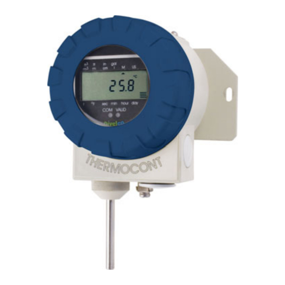
Thank you for choosing NIVELCO instrument! 1. INTRODUCTION THERMOCONT T–500/600 series 2-wire temperature transmitters are suitable for measuring, indicating and transmitting temperature of ordinary and hazardous gases, fumes, liquids and masses. The Pt100 sensor of the unit is accommodated in normal or plastic-coated stainless-steel tube manufactured with different intrusion length end process connection. -
Page 4: Technical Data
3. TECHNICAL DATA 3.1 General Data TV-- TR-- TT-- TL-- TW-- TB-- TW-- Range –50…+200 °C (–58…+392 °F) –50…+600 °C (–58…+1112 °C) Probe Pt100 sensor in PFA-coated St. St. (DIN 1.4571) tube Pt 100 sensor in St. St. (DIN 1.4571) tube Maximum pressure ** 2.5 MPa (25 bar) in +20 °C (+68 °F) ;... -
Page 5: Additional Data For Ex Approved Versions
3.2 Additional Data For Ex Approved Versions T–5–6 Ex T–5–A Ex T–5–C Ex Type T–5–8 Ex T–5–B Ex T–5–D Ex Protection mode Intrinsically safe Flame proof casing Flame proof casing and intrinsically safe Protection mark II 1 G Ex ia IIB T6...T1 Ga II 2 G Ex d IIB T6…T1 Gb II 1/2 G Ex d ia IIB T6…T1 Ga/Gb = 30 V... -
Page 6: Accessories
OUSING POSITIONS ERSION FOR WALL MOUNTING Without sensor With sensor TW–00– TW–0– Requirement for housing position other than ‘A’; should be specified with the order 3.4 Accessories Installation and Programming Manual Warranty Card, EU declaration of conformity, ... -
Page 7: Wiring
4.1 Wiring Transmitters are used in 2-wire systems with power supply of 10…36 V DC. Resistance of the units in the loop depends on the voltage of the power supply. For wiring shielded cable suggested in the Technical Data should be used. ... -
Page 8: Putting Into Operation, Programming
parameters set previously. The new, modified parameters will only be 5. PUTTING INTO OPERATION, PROGRAMMING effective after returning to the Measurement Mode Transmitter installed and wired correctly will operate after powering according to If the transmitter is left in Programming Mode by mistake, it will automatically the Manufacturer’s (Default) or to the last settings. -
Page 9: Steps Of Programming
5.1.2 Steps of programming Programming will be performed by pressing and releasing the relevant one or two keys (simultaneously). The following description is for overview only, detailed programming is to find in 5.1.3 For entering calibration value decimal point will y or yy parameter address (0, 1, …19) automatically turn up. -
Page 10: Parameters - Descriptions And Programming
5.1.3 Parameters – descriptions and programming - - - a Assignment of the (lowest) measured temperature to 4 mA - - - a Assignment of the (highest) measured temperature to 20 mA The lowest and highest (limit) value of the temperature range is to be assigned to the 4 and 20 mA output current. This can be performed by two methods a: manually i.e. - Page 11 P11: - c - - Noise suppression and displayed value Noise suppression Displayed value 50 Hz Temperature (°C or F see P10) 60 Hz FACTORY DEFAULT: 0 0 P12: - - - a Error indication Find explanation of errors in 5.2 Error indication 3.8 mA 22 mA...
-
Page 12: Error Codes
(Returned Equipment Handling Form) must be filled and enclosed in the parcel. Download it from our website www.nivelco.com. The device must be sent back with a declaration of decontamination. A statement must be provided in the declaration that the decontamination process was successfully completed and that the device is clean from any hazardous substances.
Need help?
Do you have a question about the THERMOCUT TT Series and is the answer not in the manual?
Questions and answers