Table of Contents
Advertisement
Quick Links
TT-, TV-, TW-, TB-, TL-, TR-
TEMPERATURE TRANSMITTERS
INSTALLATION AND PROGRAMMING MANUAL
1. Edition
0 4 0 8
Manufacturer:
NIVELCO Process Control Co.
H-1043 Budapest, Dugonics u. 11.
Phone: -369-7575 ♦ Fax: -369-8585
e-mail:sales@nivelco.com ♦ www.nivelco.com
♦
BKI 04 ATEX 113X
tbj5242a0600p_01.doc♦ 1 / 16
Advertisement
Table of Contents

Subscribe to Our Youtube Channel
Related Manuals for NIVELCO THERMOCONT TT Series


Summary of Contents for NIVELCO THERMOCONT TT Series
- Page 1 TT-, TV-, TW-, TB-, TL-, TR- TEMPERATURE TRANSMITTERS INSTALLATION AND PROGRAMMING MANUAL 1. Edition 0 4 0 8 Manufacturer: NIVELCO Process Control Co. H-1043 Budapest, Dugonics u. 11. Phone: -369-7575 ♦ Fax: -369-8585 e-mail:sales@nivelco.com ♦ www.nivelco.com ♦ BKI 04 ATEX 113X...
- Page 2 ♦ tbj5242a0600p_01.doc ♦ 2 / 16 BKI 04 ATEX 113X...
- Page 3 ♦ tbj5242a0600p_01.doc ♦ 3 / 16 BKI 04 ATEX 113X...
-
Page 4: Table Of Contents
C O N T E N T S 1. INTRODUCTION ......................................... 5 2. ORDER CODES........................................5 3. TECHNICAL DATA......................................6 3.1 G ......................................6 ENERAL 3.2 A ............................7 DDITIONAL PPROVED ERSIONS 3.3 D ......................................... 8 IMENSIONS 3.4 A ....................................... 9 CCESSORIES 4. -
Page 5: Introduction
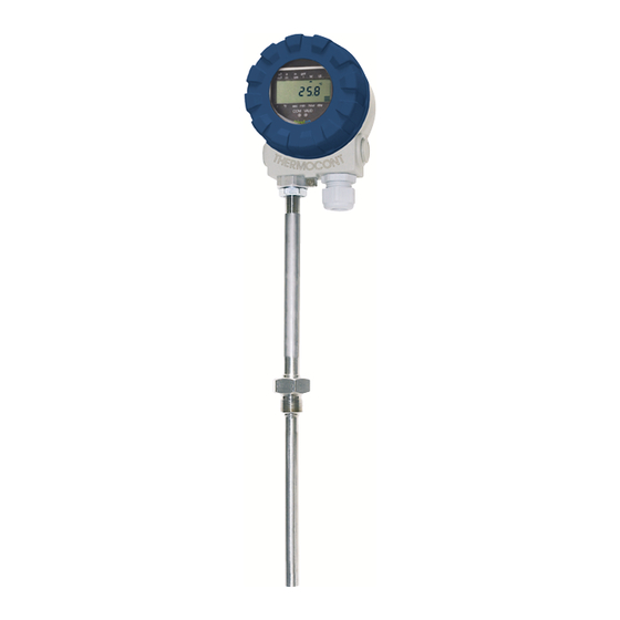
Thank you for choosing NIVELCO instrument We are sure that you will be satisfied throughout its use! 1. INTRODUCTION THERMOCONT T-500/600 series 2-wire temperature transmitters are suitable for measuring, indicating and transmitting temperature of ordinary and hazardous gases, fumes, liquids and masses. The Pt100 sensor of the unit is accommodated in normal or plastic coated stainless steel tube manufactured with different intrusion length end process connection. -
Page 6: Technical Data
3. TECHNICAL DATA 3.1 G ENERAL TV - TR - TT - TL - TW - TB - T W- ° ° ° ° Range C...+200 C...+600 Probe Pt 100 sensor in PFA coated St. St. (DIN 1.4571) tube Pt 100 sensor in St. St. (DIN 1.4571) tube Maximum pressure ** 2.5 MPa (25 bar) in +20 °C ;... -
Page 7: Additional Data For E X Approved Versions
3.2 A DDITIONAL PPROVED ERSIONS – 5 – 6Ex – 5 -AEx – 5 -CEx Type – 5 – 8Ex – 5 -BEx – 5 -DEx Protection mode Intrinsically safe Flame proof casing Flame proof casing and intrinsically safe Protection mark II 1 G EEx ia IIB T6...T1 +600°C II 2 G EEx d IIB T6...T1 +600°C II 1/2 G EEx d ia IIB T6...T1 +600°C... -
Page 8: Dimensions
3.3 D IMENSIONS R D I N A R Y T Y P E S X P L O S I O N P R O O F T Y P E S -50 °C… +200 °C -50 °C… +600 °C NSTRINSICALLY SAFE LAME PROOF CASING Ø20... -
Page 9: Accessories
OUSING POSITIONS ERSION FOR WALL MOUNTING "A" "B" "C" "D" Without sensor With sensor T W – 00 – T W – 0 – Requirement for housing position other than„A; should be specified with the order 3.4 A CCESSORIES • Installation and Programming Manual •... -
Page 10: Wiring
4.1 W IRING • Transmitters are used in 2-wire systems with power supply of 10 … 36 V DC. Resistance of the units in the loop depends on the voltage of the power supply. 4 3 2 1 4 3 2 1 –... -
Page 11: Putting Into Operation, Programming
5. PUTTING INTO OPERATION, PROGRAMMING COM LED Display unit comnnector Transmitter installed and wired correctly will operate after powering according to the Manufacturer’s (Default) or to the last settings. 4 ... 20 mA loop current Operability is indicated by lighting of the LED VALID. and supply HART I- I+ 1/2”... -
Page 12: Display And Keys Of The Sap 202 Display Module
5.1.1 Display and keys of the SAP 202 display module Symbols on the frame • metric system Programming Programming • calculation system keys keys • °F temp. in Fahrenheit • LED indication 4...20mA • indicating HART communication • SAP-2 VALID indicating operability Symbols on the screen display •... -
Page 13: Steps Of Programming
5.1.2 Steps of programming Programming will be performed by pressing and releasing the relevant one or two keys (simultaneously). The following description is for overview only, detailed programming is to find in 5.1.3 y or yy parameter address (0, 1, …19) For entering calibration value decimal point will yy :xxxx sign... -
Page 14: Parameters - Descriptions And Programming
5.1.3 Parameters – descriptions and programming - - - a Assignment of the (lowest) measured temperature to 4 mA - - - a Assignment of the (highest) measured temperature to 20 mA The lowest and highest (limit) value of the temperature range is to be assigned to the 4 and 20 mA output current. This can be performed by two methods a: manually i.e. - Page 15 P11: - c - - Noise suppression and displayed value Noise supression Displayed value 50 Hz Temperature (°C or F see P10) 60 Hz FACTORY DEFAULT: 0 0 P12: - - - a Error indication Find explanation of errors in 5.2 Error indication 3.8 mA 22 mA...
-
Page 16: Error Codes
COMMUNICATION HART capable transmitters would communicate with the Nivelco made MULTICONT interface according to the HART standard. MULTICONT provides for the powering and makes possible remote programming of the transmitters while (transmitter parameter values and) measurement data can be forwarded from the MULTICONT on RS485 line.
Need help?
Do you have a question about the THERMOCONT TT Series and is the answer not in the manual?
Questions and answers