Table of Contents
Advertisement
Advertisement
Table of Contents

Subscribe to Our Youtube Channel
Related Manuals for NIVELCO EasyTREK SP-300


Summary of Contents for NIVELCO EasyTREK SP-300
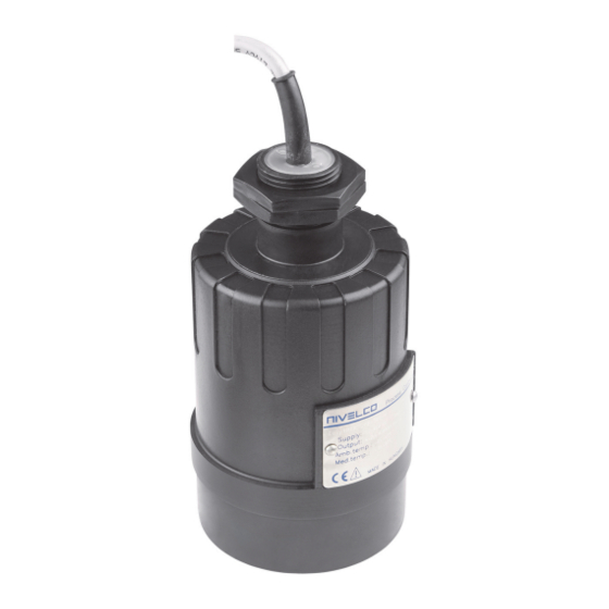
- Page 1 EasyTREK SP-300, SP-300 Ex two-wire compact ultrasonic level transmitter Manufacturer NIVELCO Process Control Co. H-1043 Budapest, Dugonics u. 11. Tel.: (36-1) 889-0100 Fax: (36-1) 889-0200 E-mail: sales @nivelco.com www.nivelco.com BKI16ATEX0017X spa3804a0600p_08 1 / 44...
- Page 2 Min. measuring distance BASIC CONCEPTS AND ELEMENTS OF ULTRASONIC MEASUREMENT DIST = Distance (measured) LEV = Level (calculated: H-DIST ) VOL = Volume (calculated from LEV) Measurement Device data Application data 2 / 44 BKI16ATEX0017 spa3804a0600p_08...
-
Page 3: Table Of Contents
CONTENTS 1. INTRODUCTION ................5 5.3.6. Data logger ................26 5.3.7. Volume (content) measurement ..........30 5.3.8. Open channel flow measurement ..........31 2. TECHNICAL DATA ..............6 5.3.9. 32-Point linearisation ..............37 2.1 General data ..................6 5.3.10. Informational parameters (read out parameters) ....38 2.2 Additional data for ex certified devices .......... - Page 4 BKI16ATEX0017X spa3804a0600p_08 4 / 44...
-
Page 5: Introduction
We are sure that you will be satisfied throughout its use. 1. INTRODUCTION Application A Total beam angle of 5-7 at -3 dB as is featured by most of Nivelco’s SenSonic transducers ensuring a reliable measurement in narrow silos with The EasyTREK compact ultrasonic level transmitters from NIVELCO are uneven side walls as well as in process tanks with various protruding objects. -
Page 6: Technical Data
Electrical protection Class III SELV (1) For pressures below 1 bar representative of Nivelco should be consulted. (2) Under optimal circumstances of reflection and stabilised transducer temperature. (3) Only partial operation is provided. Realible operation without any restrictions is guaranteed at >13.4V terminal voltage. -
Page 7: Special Data
2.3 S PECIAL DATA PP, PVDF PTFE PECIAL DATA FOR TRANSDUCERS ALSO APPLIES TO E MODELS Type SP-39 - SP-38- SP-37- SP-36- SP-34- SP-32- Transducer material PP, PVDF PTFE PP, PVDF PTFE PP, PVDF PTFE PP or PVDF PP or PVDF PP or PVDF Max measuring distance * (X 4/13... -
Page 8: Dimensions
2.6 D IMENSIONS EasyTREK EasyTREK EasyTREK EasyTREK EasyTREK EasyTREK SP-39- / SP-38- / SP-37- / SP-36- / SP-34- / SP-32- / PP, PVDF, PTFE PP, PVDF, PTFE PP, PVDF, PTFE PP, PVDF PP, PVDF PP, PVDF 1” BSP 1” BSP 1”... -
Page 9: Installation
3. INSTALLATION 3.1 L IQUID EVEL EASUREMENT POSITION The ideal position of the EasyTREK is on the radius r = (0.3 … 0.5) R of the (cylindrical) tank / silo. (Take also sonic cone on page 5 into consideration.) SENSOR ALIGNMENT TEMPERATURE The sensor face has to be parallel to the Make sure that the transmitter is... - Page 10 OBSTACLES WIND Make sure that no objects (cooling pipes, bracing members, Intensive air (gas) movements in the vicinity of the ultrasonic cone thermometers etc.) protrude into the sensing cone of the ultrasonic is to be avoided. A strong draft of wind may "blow away" the beam.
-
Page 11: Open Channel Flow Measurement
Install the unit in a place defined by the characteristics of the metering channel along the longitudinal axis of the flume or weir. In case of Parshall flumes supplied by NIVELCO the location of the sensor is marked. ... -
Page 12: Putting Into Operation
„COM” IrDA logger readout, diagnostics and software upgrade Device can be reset to factory setting. Default of EasyTREK SP-300 is the following: Measurement: level (LEV) Zero level assigned to the maximum distance Current output proportional to the level ... -
Page 13: Special Conditions Of Safe Use
5.2. S PECIAL CONDITIONS OF SAFE USE Diameter of the cable should match the cable conduit. The cable outside the unit should be fixed so that it should be free of loading. The terminal box should be selected in accordance with the electrical class of the area. The device should read or programmed through IR port only outside of the explosive hazardous atmosphere because the infrared interface connected to the computer is not an explosion-proof apparatus. -
Page 14: Programming
- EView software run on the PC connected through HART modem to the loop or - Nivelco made MultiCONT multi-channel process control unit. Since these access methods differ in their form and handling present manual does not review them. The information is contained in the relevant descriptions and user’s manuals. - Page 15 P01: - - 1 a Measurement Mode FACTORY DEFAULT: 11 Parameter value „a” will determine the basic measurement value that will be transmitted. Subsequently values for the relays are also relating to these quantities. Measurement Transmitted value Display symbol mode Distance Distance DIST...
- Page 16 VOL% VOL%= Transmitted value (H-DIST) P40…P45 Parameters to set P01(a) P01(a) = P02(b) P02(b) ≥ X ≥ X P40…P45 100% P40…P45 A: Shortest measurable distance B: Volume (content) pertaining to the greatest measurable level C: Whole value of the vessel D: diagram valid for the default value of P10 P11 16 / 44 ...
- Page 17 P02: - c b a Calculation units FACTORY DEFAULT: 000 Temperature °C °F This table is interpreted according to P00(c), P01(a) and P02(c) and is irrelevant in case of percentage measurement [ P01(a)= 2 or 4 )] Volume Weight (set also P32) Volume flow Metric Metric...
- Page 18 P05: - - - - Minimum measuring distance (Dead zone - Close-end blocking) FACTORY DEFAULT: X as per chart The range, beginning with the sensor’s surface, within which (due to the physical restraint of the ultrasound measurement system) measurement can not be made, is called the dead zone.
- Page 19 P06: - - - - Far-end blocking FACTORY DEFAULT: 0 Far-end blocking is the range below the level set in parameter P06. The far-end blocking can be used to avoid disturbing effect of stirrer or heaters at the bottom of the tanks. Detecting echoes in this range the unit provides special signals.
-
Page 20: Current Output
5.3.2. C URRENT UTPUT P08: - - - - Fixed current output FACTORY DEFAULT: 0 By this step the output current can be set for a fix value selected from between 3.8 mA and 20.5 mA. This function is not operational as per the factory default: 0. -
Page 21: Relay Output
5.3.3. R ELAY UTPUT P13: - - - a Relay function Relay function Also set: DIFFERENTIAL LEVEL CONTROL P14, P15 Level (Hysteresis control) There is a need to set (in level Relay is energised if the measured or min 20mm) hysteresis between calculated value exceeds the value set in P14 P14 and P15 Time... -
Page 22: Digital Communication
5.3.4. D IGITAL COMMUNICATION P19: - - - a Short (HART) address of the unit FACTORY DEFAULT: 2 These addresses with 0 … 15 are, in accordance with the HART standard, for distinguishing units in the same loop. Address: 0 current output of 4 … 20 ma operational ... - Page 23 P25: - - - a Selection of Echo within the measuring window FACTORY DEFAULT: 0 A so-called measuring window is formed around the echo signal. The position of this measuring window determines the flight time for calculation of the distance to the target. (the picture below can be seen on the test oscilloscope) Received Echo 1.
- Page 24 P28 - - - a Echo loss indication FACTORY DEFAULT: 0 Echo loss indication Remark During short echo-loss (for the period of twice the time set in P20) analogue output will hold last value. After this period the current value according to the setting in P12 and via HART ERROR CODE 2 will be transmitted.
- Page 25 P29 - - - - Blocking out of disturbing object FACTORY DEFAULT: 0 One fixed object in the tank, disturbing the measurement, can be blocked out. By the use of the Echo Map (P70) the precise distance of disturbing object can be read out. This value should be entered in this parameter. P31: - - - - Sound velocity at 20C (m/s or ft/s depending on P00(c) FACTORY DEFAULT:: 343,8 (m/s), 1128 (ft/s)
-
Page 26: Data Logger
5.3.6. D ATA LOGGER The logger of the device can store 12288 events. The registry is in a non-volatile (FLASH) memory, so the registry will retain its contents even in case of a power failure. The on-board clock of the device is protected against short power-outs, and keeps working for at least 15 days after the device is switched off. - Page 27 P34: - cba Logging mode Operating mode Parameters to be programmed No logging Linear logging P35 – interval (minute) Event-controlled logging when the primary value changes P35 – absolute value of variation Event-controlled logging when the primary value changes P35 – variation in % Event-controlled logging when the primary value gets out of range P35, P36 –...
- Page 28 P35-36: Log value 1 and log value 2 P34a Operating mode Function of P35 and P36 No logging Linear logging P35 = 0 One entry after every measurement cycle. P35 <> 0 Logging interval (minutes) Value is indifferent Event-controlled logging when the primary Absolute value of the change in the primary measured value (according to value changes P01a)
- Page 29 M8421 * Recommended RS232-USB adapters for using the USB port: STLab: USB-RS232 MOXA: NPort-U1110, UPort 1110 After connecting the adapters start DataScope program. The program and the User’s Manual can be found on the website of NIVELCO. BKI16ATEX0017X...
-
Page 30: Volume (Content) Measurement
5.3.7. V OLUME CONTENT MEASUREMENT P40: - - ba Tank shape FACTORY DEFAULT: Tank shape Also to be set Standing cylindrical tank shape (value of “b” as below) P40 (b), P41 Attention! Standing cylindrical tank with conical bottom P41, P43, P44 The value „a”... -
Page 31: Open Channel Flow Measurement
5.3.8. O PEN CHANNEL FLOW MEASUREMENT P40: - - b a Devices, formula, data FACTORY DEFAULT: Devices, formula, data Also to be set Type Formula Qmin [l/s] Qmax [l/s] “P” [cm] GPA-1P1 Q [l/s]= 60.87*h 0.26 5.38 1.552 GPA-1P2 Q [l/s]= 119.7*h 0.52 13.3 1.553... - Page 32 P41-45: Flume/weir dimensions FACTORY DEFAULT: P40=00 . Nivelco Parshall flumes (GPA1P1 … GPA-1P9) For further details see the Manual of the Parshall flume EasyTREK EasyTREK P40=09 General Parshall flume 0.305 < P42(width) <2.44 ...
- Page 33 P40= 10 Palmer-Bowlus (D/2) flume /s]= f(h1/P41) * P41 , where h1[m]= h+(P41/10) P41 m D/10 P40= 11 Palmer-Bowlus (D/3) flume /s]= f(h1/P41) * P41 , where h1[m]= h+(P41/10) P41 m D/10 P40= 12 Palmer-Bowlus (rectangular) flume /s]= C * P42 * h , where C= f(P41/P42) P41 m, P42 m...
- Page 34 P40= 13 15cm Khafagi Venturi flume Q [m /s] = 1.744 P42 h + 0.091 h P42 m h [m] EasyTREK EasyTREK P40= 14 P40=14 Bottom step weir 0.0005 < Q [m /s] < 1 0.3 < P42 [m] < 15 0.1 <...
- Page 35 P40= 16 Trapezoidal weir P40=16 0.0032 < Q [m /s] < 82 20 < P41[°] < 100 0.5 < P42 [m] < 15 0.1 < h [m] < 2 Q [m /s] = 1.772 P42 h + 1.320 tg(P41/2) h 2.47 Accuracy: ...
- Page 36 P40= 19 P40=19 THOMSON (90°-notch) weir 0.0002 < Q [m /s] < 1 0.05 < h [m] < 1 /s] = 1.320 h 2.47 Accuracy: P40= 20 P40=20 Circular weir 0.0003 < Q [m /s] < 25 0.02 < h [m] < 2 /s] = m * b ...
-
Page 37: 32-Point Linearisation
5.3.9. 32-P OINT LINEARISATION P47: - - - a Linearisation FACTORY DEFAULT: 0 Linearisation is the method of assigning requested (calibrated or calculated) level, volume or flow to values measured by the transmitter. It can be used for instance if the sound velocity is not known (LEVELLEVEL) or in the case of tank with other shape than under 6.4 or open channel other than under 6.5 (LEVEL ... -
Page 38: Informational Parameters (Read Out Parameters)
5.3.10. I NFORMATIONAL PARAMETERS READ OUT PARAMETERS P60: - - - - Overall operating hours of the unit (h) P61: - - - - Time elapsed after last switch-on (h) P62: - - - - Operating hours of the relay (h) P63: - - - - Number of switching cycles of the relay P64: - - - -... -
Page 39: Additional Parameters Of The Flow Metering
5.3.11. A DDITIONAL PARAMETERS OF THE FLOW METERING P76: - - - - Head of flow (LEV) (Read only parameter) The Headwater value can be checked here. This is the “h” value in the formula for flow calculation. P77: - - - - TOT1 volume flow (resettable) totalised... -
Page 40: Maintenance And Repair
The need for cleaning of the sensor head may occur. Cleaning should be performed by utmost care where scraping or denting of the transducer have to be avoided. Repair under or after the guarantee period should only be carried out by Nivelco. Devices for repair should only be returned duly cleaned and disinfected. -
Page 41: Error Codes
7. ERROR CODES Error Error description Causes and solutions Code Memory error Contact local agent No Echo Echo loss See Action 5 and 6 Hardware error Contact local agent Display overflow Check settings Sensor error or improper installation/mounting, level in Verify sensor for correct operation and check for correct mounting the dead band according to the User’s Manual... -
Page 42: Parameter Table
8. PARAMETER TABLE Par. Page Description Value Par. Page Description Value d c b a d c b a Application/Engineering Units Echo loss indication Measurement Mode Blocking out a disturbing object Calculation units – Sound velocity values in different gases Maximum Measuring Distance Specific gravity Minimum Measuring Distance... - Page 43 Page Description Value Description Value Par. Par. Page d c b a d c b a – TOT2 volume flow totalised – Free space of the logger in percent – – – – Overall operating hours of the unit – Time elapsed after last switch-on –...
-
Page 44: Sound Velocity Values In Different Gases
349.1 Carbon tetrachloride Nitrogen 212.7 Chlorine Nitrogen monoxide 213.4 328.6 Dimethyl ether Oxygen 327.4 246.5 Ethane Propane Sulphur hexafluoride 137.8 spa3804a0600p_08 November 2017 Nivelco reserves the right to change technical specifications without notice. 44 / 44 BKI16ATEX0017X spa3804a0600p_08...
Need help?
Do you have a question about the EasyTREK SP-300 and is the answer not in the manual?
Questions and answers