Table of Contents
Advertisement
Quick Links
Advertisement
Table of Contents

Related Manuals for NIVELCO THERMOPOINT TM/J-500


Summary of Contents for NIVELCO THERMOPOINT TM/J-500
- Page 1 tmh5554a0600p_06 tmh555en2106p 1 / 28...
- Page 2 CERTIFICATES Reference document number tmh5554m0600p_06 BKI ATEX, Certificate No.: BKI16ATEX0004X/1 2 / 28 tmh5554a0600p_06 tmh555en2106p...
- Page 3 tmh5554a0600p_06 tmh555en2106p 3 / 28...
- Page 4 4 / 28 tmh5554a0600p_06 tmh555en2106p...
-
Page 5: Table Of Contents
TABLE OF CONTENTS INTRODUCTION ....................6 5.3. ..........17 ESCRIPTION OF PROGRAMMABLE FEATURES ORDER CODES (NOT ALL COMBINATIONS ARE POSSIBLE!) ....7 5.3.1 Basic measurement settings ................17 TECHNICAL DATA ..................8 ... -
Page 6: Introduction
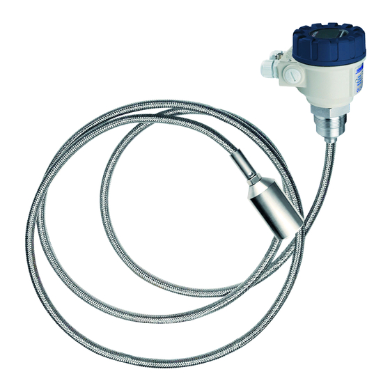
Thank you for choosing a NIVELCO instrument! 1. INTRODUCTION THERMOPOINT TM / J−500 / −600 / −700 series 2-wire temperature transmitters are suitable for continuous multipoint measurement, indication, and transmission of the temperature of regular and hazardous liquids, powders, and granular solids. The sensor of the instrument is built into a rigid or a flexible tube or an antistatic plastic-coated steel wire rope, depending on the measured material and insertion length. -
Page 7: Order Codes (Not All Combinations Are Possible!)
2. ORDER CODES (NOT ALL COMBINATIONS ARE POSSIBLE!) THERMOPOINT multipoint temperature transmitters − Ex * − − ABLE ERSION ROBE ROCESS CONNECTION OUSING UMBER OF SENSORS UTPUT LENGTH Multipoint transmitter 1" BSP Aluminum 1 m / 31 m HART ® 1"... -
Page 8: Technical Data
3. TECHNICAL DATA Rigid probe version Flexible probe version Flexible, plastic-coated probe version Type TR, TA, TJ−− TK, TE, TN, TL−− TH, TC, TF, TG−− Insertion length 1…4 m (3.3…13 feet) 1…50 m (3.3…164 feet) 1…50 m (3.3…164 feet) Highest medium pressure 25 bar (2.5 MPa, 363 psi) 16 bar (1.6 MPa, 232 psi) 3 bar (0.3 MPa, 43.5 psi) -
Page 9: E X Information
3.1. X INFORMATION T−5−5Ex T−5−8Ex, T−7−8Ex Type T−−6Ex T−7−5Ex T−5−9Ex, T−7−9Ex Ex marking II 1 G Ex ia IIB T6…T4 Ga II 1 D Ex ia IIIC T85ºC Da II 1 D Ex ta IIIC T105ºC Da II 1/2 D Ex ta/tb IIIC T85ºC Da/Db Waiting time for opening ... -
Page 10: Dimensions
3.2. IMENSIONS For solids For liquids Position of sensors TH, TC, TF, TN, TL, TK, TR, TA, TG−− TE−− TJ−− 10 / 28 tmh5554a0600p_06 tmh555en2106p... -
Page 11: Accessories
(Returned Equipment Handling Form) must be filled and enclosed in the parcel. Download it from our website www.nivelco.com. The device must be sent back with a declaration of decontamination. A statement must be provided in the declaration that the decontamination process was successfully completed and that the device is clean from any hazardous substances. -
Page 12: Installation And Wiring
4. INSTALLATION AND WIRING During the installation, the following instructions must be considered: Depending on the thermal characteristics of the measured material the sensor must be installed proper distance from the silo wall, Depending on the cross section of the silo several sensors should be installed, ... -
Page 13: Commissioning And Programming
HART (REMOTE PROGRAMMING) communication system remotely. The SAP−300 is a 64x128 dot-matrix LCD display, which can be plugged into the transmitter. (The unit is universal, it can be used in other NIVELCO devices, provided that the system software supports SAP−300.) Warning! The SAP−300 module is based on LCD technology! Make sure it is not exposed to continuous heat or direct sunlight to avoid... -
Page 14: Displaying Measurements With The Sap−300 Display Module
5.1. SAP−300 ISPLAYING MEASUREMENTS WITH THE DISPLAY MODULE Legend: 1. Measured temperature values. From top to bottom, from left to right in increasing order. The instrument can handle up to 15 sensors. The six horizontal lines indicate the absence of the sensor or a sensor error. The #1 sensor is the closest to the electronic housing;... - Page 15 Information screens Press the button to cycle between information screens. 1. General information (DEV. INFO): overall running time (OV. RUN TIME), uptime since power on (RUN TIME), type of interface (INTERFACE). 2. Sensor information: number of temperature sensors in the probe (TOTAL SENSOR COUNT), number of the sensor with the highest number (RANGE).
-
Page 16: Programming With The Sap−300 Display Module
5.2. SAP−300 ROGRAMMING WITH THE DISPLAY MODULE When entering the menu, the device copies the current parameter set, and all changes are made in this duplicate. The instrument keeps measuring and transmitting values in accordance with the current (and intact) parameter set while programming. After exiting the menu, the instrument replaces the original parameters with the new parameter set and starts measuring in accordance with the new parameters. -
Page 17: Menu Structure
Edit windows Edit windows are used for modifying numeric parameter values. The selected character can be changed using the buttons. The cursor can be moved to the left using the button. The direction of the cursor movement through the digits is right to left and the items wrap around. Changed values can be validated by pressing the E button. -
Page 18: Temperature Measurement Units
5.3.1.2 Temperature measurement units Parameter: P02: a Menu path: BASIC SETUP / UNIT / TEMPERATURE UNIT Default value: ºC Description: Unit of the temperature measurement ºC ºF 5.3.1.3 Damping time Parameter: Menu path: BASIC SETUP / DAMPING TIME Default value: 0 sec Description:... -
Page 19: Output Current Error Mode
5.3.2.4 Output current error mode Parameter: P12: a Menu path: OUTPUT SETUP / ANALOG OUTPUT / ERROR MODE Default value: 20.5 mA Description: Error indication on the current output. Error indication is OFF. The device transmits in accordance to the last calculation. ... -
Page 20: Service Functions
5.3.4 Service functions 5.3.4.1 Security codes User security code Parameter: Menu path: SERVICE / SECURITY / USER LOCK Description: Setting or unlocking the user security code. The device can be protected against unauthorized programming with a 4-digit PIN code. If either of the digits differs from 0 the code is active. -
Page 21: Temperature Simulation
5.3.4.3 Temperature simulation This function helps the user to check the outputs and the connected processing units After finished editing the settings, the unit must be returned into Measurement mode to start the simulation. Temperature simulation mode Parameter: P84: a Menu path: SERVICE / TEMP. -
Page 22: Load Default Values
Temperature simulation cycle Parameter: Menu path: SERVICE / TEMP. SIMULATION / TIME Default value: 60 sec Description: Cycle period of the simulation Bottom value of the Temperature simulation Parameter: Menu path: SERVICE / TEMP. SIMULATION / BOTTOM VALUE Default value: –10 ºC Description: Lowest value of the simulation... -
Page 23: Multi Cont Process Controller
5.4. RS485 CONT COMMUNICATION VIA ULTI PROCESS CONTROLLER 5.4.1 Remote data query via HART ® protocol Knowing the HART commands of the transmitters, there is a possibility to query the data of the connected transmitters with the help of USER RS485 interface of MultiCONT process controller (the MultiCONT acts as a bridge). -
Page 24: Remote Data Query With Modbus Protocol
5.4.2 Remote data query with MODBUS protocol Knowing the HART commands of the transmitters, there is a possibility to query the data of the connected transmitters with the help of USER RS485 interface of MultiCONT process controller (the MultiCONT acts as a bridge). This can be done the following way: the MASTER inserts the MODBUS frame to the data field of the HART frame, which is sent to the transmitters by the MultiCONT, ... -
Page 25: Example Of Data Query With Modbus Protocol
5.4.2.1 Example of data query with MODBUS protocol HART Transmitter Number of sensors in a probe Unsigned 16 0x7001 0x7041 0x7081 0x70C1 0x7101 0x7141 0x7181 0x71C1 0x7201 0x7241 0x7281 0x72C1 0x7301 0x7341 0x7381 (1…15) Dimension Unsigned 16 0x7002 0x7042 0x7082 0x70C2 0x7102 0x7142... -
Page 26: Error Codes
6. ERROR CODES Message on the screen Error description Procedure MEMORY ERROR Memory error in the electronics Contact the dealership! NO INPUT SIGNAL Hardware error Contact the dealership! EE COM. ERROR Hardware error Contact the dealership! MATH. OVERLOAD Display overflow Check the settings! SENSOR NOT FOUND Hardware error... -
Page 27: Menu Map
7. MENU MAP tmh5554a0600p_06 tmh555en2106p 27 / 28... - Page 28 March 2021 NIVELCO reserves the right to change anything in this manual without notice! 28 / 28 tmh5554a0600p_06 tmh555en2106p...
Need help?
Do you have a question about the THERMOPOINT TM/J-500 and is the answer not in the manual?
Questions and answers