NIVELCO EchoTREK S-300 Installation And Programming Manual
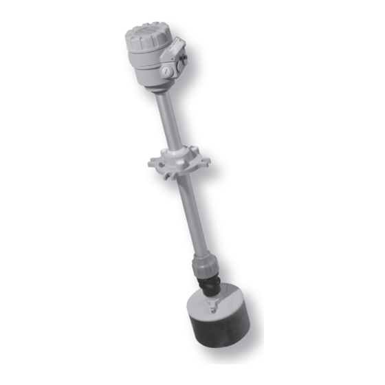
Compact ultrasonic level transmitter series for free flowing solids
Hide thumbs
Also See for EchoTREK S-300:
- User and programming manual (50 pages) ,
- User manual (12 pages)
Table of Contents
Advertisement
Quick Links
Advertisement
Table of Contents

Related Manuals for NIVELCO EchoTREK S-300


Summary of Contents for NIVELCO EchoTREK S-300
- Page 1 EchoTREK S-300 compact ultrasonic level transmitter series for free flowing solids Manufacturer: NIVELCO Process Control Co. H-1043 Budapest, Dugonics u. 11. Phone: (36-1) 889-0100 Fax: (36-1) 889-0200 E-mail: sales @nivelco.com www.nivelco.com BKI16ATEX0020X ♦ sbd31j0a0600p_03♦ 1 / 48...
- Page 2 PRINCIPLES ULTRASONIC LEVEL MEASUREMENT Angle of repose DIST=distance (measured) LEV=( level calculated H-DIST) VOL= volume (calculated from LEV) 2 / 48 ♦ BKI16ATEX0020X ♦ sbd31j0a0600p_03...
-
Page 3: Table Of Contents
C O N T E N T S 5.3...................16 ROGRAMMING 1. INTRODUCTION..................5 5.3.1. Basic steps of the programming ..........18 2. TECHNICAL DATA................6 5.3.2. Current output scaling..............19 2.1.................... 6 ENERAL DATA 5.3.3. QUICKSET.................20 2.2....................6 5.3.4. Full Parameter Access...............22 PECIAL DATA 5.4. - Page 4 4 / 48 ♦ BKI16ATEX0020X ♦ sbd31j0a0600p_03...
-
Page 5: Introduction
A total beam angle of 5° at –3 dB is a feature of all NIVELCO’s ultrasonic sensors designed for the level measurement of free flowing solids. This uniquely narrow beam angle ensures reliable measurement in narrow silos with uneven side walls or sometimes even in the presence of dusting. Furthermore, as a result of the narrow beam angle –... -
Page 6: Technical Data
2. TECHNICAL DATA 2.1. G ENERAL DATA Type EchoTREK SBD / STD–3 J– EchoTREK SBD / STD–3 J– Closed cell Polyurethane foam sensor face (PUR) Closed cell Polyurethane foam sensor face (PUR) Transducer material PP and Aluminum transducer housing and fitting Aluminum transducer housing and fitting Total beam angle (-3dB) 5°... -
Page 7: Sap-100 Programming And Display Module
2.3. SAP-100 P ROGRAMMING AND ISPLAY MODULE Field display 6-digit LCD display for measurement value, engineering unit and bargraph Ambient temperature -25 °C…+60 °C Housing material Fibre-glass reinforced plastic (PBT) 2.4. A CCESSORIES Installation and Programming Manual Warranty Card Declaration of Conformity EView configuration software and description on CD (only for S D –... -
Page 8: Dimensions
2.6. D IMENSIONS Ball-joint housing S D–33J- S D–34J– S D–31J– S D–31J– Ex (view from above) Ball joint Ball joint Ball joint housing housing housing 8 / 48 ♦ BKI16ATEX0020X ♦ sbd31j0a0600p_03... -
Page 9: Installation
3. INSTALLATION LACEMENT Sunshade To find the ideal position for the location of the EchoTREK level transmitter various considerations should be made. The transmitter should not be installed in the centre of the tank/silo when the tank roof is dome shaped or conical. - Page 10 Mounting EchoTREK versions S -33J- and S -34J- 1. Check the split flange for matching the bore-holes with that of the counter-flange on the silo 2. Remove the split insertion from the flange and put the flange around the aiming arm between the sensor and the Alu-base. Slide the split insertion back to its place and screw the ball-joint housing to the flange with the 4 pcs M 12 bolts to such an extent that will allow free movement of the aiming arm through and tilting by the ball joint for the aiming process.
- Page 11 IAMETER OF THE HICKNESS OF OPENING THE ROOF 160 mm 110 mm 190 mm 150 mm 230 mm 200 mm 300 mm 280 mm 340 mm 300 mm Illustration for mounting BKI16ATEX0020X ♦ sbd31j0a0600p_03♦ 11 / 48...
-
Page 12: Wiring
4. WIRING To access the electric connection point, unscrew the bolt on the side of the Earthing screw electronics housing. Use cable with a wire cross- section of 0.5 … 2.5 mm Place of M20x1.5 Electric connections may be carried out by using a single or two cables. Wires in different groups (A, B, C;... -
Page 13: Putting Into Operation, Adjusting, Programming
5. PUTTING INTO OPERATION, ADJUSTING, PROGRAMMING 5.1. P UTTING INTO OPERATION USAGE After switching on the correctly wired unit the transducer begins to click audibly. In about 20 … 50 s the ECHO LED goes on and a signal between 4 – 20 mA appears on the current output. -
Page 14: The Sap-100 Programming And Display Module
5.1.1. The SAP-100 programming and display module The plug-in type programming and display module can be removed or plug-in during the operation of the EchoTREK level transmitter. The module has 4 push buttons and a special multifunction LCD display. The measured values are displayed in the central line of the display. The engineering units are displayed in the bottom or top lines, or indicated by the arrow pointing the units on the frame of the display. -
Page 15: Usage And The Indications Of The Sap-100 Programming And Display Module In Measurement Mode
5.1.2. Usage and the indications of the SAP-100 programming and display module in measurement mode The device is in Measurement Mode, when PROG is not shown on the display. This case the display shows the measurement value which can be changed according to the following steps. -
Page 16: Special Conditions For Safe Use
5.2. S PECIAL ONDITIONS FOR SAFE USE The equipment is not allowed to be installed in the dust path of the pneumatic filling! The apparatus nor any part of it is not suitable as a fire resistant barrier for the Zone 20 area. The instrument should be grounded by all its grounding screws to the EP system in order to avoid electrostatic charges and due to the Class I. - Page 17 SAP-100 ROGRAMMING MODES OFFERED BY THE PROGRAMMING AND DISPLAY MODULE (5.3.2.) URRENT OUTPUT SCALING Assign the level values to the current output (4 and 20 mA). All the other parameters remain unchanged. (5.3.3.) UICKSET Recommended as a simple and fast way to set up the EchoTREK by 8 basic parameters This menu driven programming mode supports the following basic settings: Engineering unit for the display (metric or US) Maximum measuring distance (H)
-
Page 18: Basic Steps Of The Programming
5.3.1. Basic steps of the programming Local programming of the unit can be performed with the four push buttons of the SAP-100 module. The followings give an overview about handling the programming module and the detailed programming instructions are covered in the 5.3.2, 5.3.3, 5.3.4 and the 5.4 chapters. INGLE KEY PRESSING The functions of the keys became active after the button is released. -
Page 19: Current Output Scaling
5.3.2. Current output scaling This programming mode is the simple and fast way to modify the scaling of the current output. For changing all parameters other than those assigned to 4 and 20 mA use either the QUICKSET (5.3.2) or the Full Parameter Access (5.3.3). Measuring is going on during programming in accordance with the old parameter set. -
Page 20: Quickset
5.3.3. QUICKSET TREK ECOMMENDED AS A SIMPLE AND FAST WAY TO START UP QUICKSET programming is aided by 8 screens to set the 8 basic parameters of the device if the required application is not a challenging one. The instructions of this programming mode are also to be found, below the screw cover, on the front panel of the EchoTREK. - Page 21 xxxx – level value assigned to 4 mA current output Manual: set the level value manually (by using UP / DOWN / NEXT keys) and save it (by ENTER ) counted from the maximum measuring distance (H) which is to be assigned to 4 mA output current 4:xxxx Automatic : use the “GET LEVEL”...
-
Page 22: Full Parameter Access
5.3.4. Full Parameter Access To access all features provided by the EchoTREK Description of all parameters can be found under the 5.4 chapter. PERATION ENTER + UP (press for 3 seconds) Enter into or exit from the Full Parameter Access programming mode In this programming mode, the display will indicate PROG and the following screen: yy is the Parameter Address (Pyy = P01, P02 …... -
Page 23: Arameters Escriptions And Rogramming
5.4. P – D ARAMETERS ESCRIPTIONS AND ROGRAMMING 5.4.1. Measurement Configuration P00: - c b a Application / Engineering Units NOTE! Programming of this parameter will result in loading the factory default with the corresponding engineering units! Attention! Mind the sequence! Coming to PERATING MEASUREMENT MODE... - Page 24 P01: - - b a Measurement Mode This mode determines the primary value transmitted by the current output or the HART protocol communication and the displayed value. It also determines the value which will be assigned to the relay operation. RANSMITTED ISPLAY Attention! Mind...
- Page 25 P03: - - - a Values Displayed - Rounding (DIST) display ISTANCE It is important to keep in mind that the instrument is measuring distance as basic quantity and all the other process values are calculated from this basic quantity. The resolution of the measured distance is 1 cm which is reflected on the calculated (level, volume) values.
- Page 26 P04 - - - - Maximum distance to be measured (H) The maximum distance to be measured is the only one parameter that has to be programmed for each application other than distance measurement mode. The DEFAULT value of P04 (see table below) can also be displayed by double key pressing NEXT + DOWN Values of the maximum measuring distance will be in accordance with the table below.
- Page 27 P05: - - - - Minimum measuring distance (Dead zone - Close-end blocking As basic characteristics of the ultrasonic level metering principle the EchoTREK will not accept any echo within the close-end blocking, also called dead zone. This range is the minimum measuring distance which can be measured by the level transmitter. By increasing this parameter disturbing objects and false reflections which are close to the sensor can be eliminated.
- Page 28 P06: - - - - Far-end blocking Far end blocking is used to neglect incorrect level/volume readings and output actions below a pre-set level. In the far-end of the measuring range, for example tanks with heaters or other interfering objects (sludge, cone of silo etc.) may cause faulty readings.
-
Page 29: Analogue Output
5.4.2. Analogue Output P10: - - - - Value (of distance, level or volume) assigned to 4 mA current output P11: - - - - Value (of distance, level or volume) assigned to 20 mA current output Values are interpreted according to P01(a). Please note that in case of programming for LEV % or VOL % measurement, the min. and max. value has to be entered in the relevant engineering units of LEV (m, ft) or VOL (m , ft Assignment can be made so that the proportion between the change of the (measured or calculated) process value and the change of the current... -
Page 30: Relay Output
5.4.3. Relay Output P13: - - - a Relay functions ELAY FUNCTIONS LSO SET Level Relay is energised if the measured or P14, P15 calculated value exceeds the value set DIFFERENTIAL LEVEL There is a need to set in P14 CONTROL (in level min. -
Page 31: Measurement Optimisation
5.4.4. Measurement Optimisation P20: - - - a Damping time Damping time can be used to damp the unwanted fluctuations of the output and display. LOWING OLIDS AMPING TIME RANULES OWDERS SECONDS > 2-3 mm < 1-2 mm no filtering Recommended for testing only not applicable not applicable... - Page 32 P23: - - - a Angle of repose (repose formation) This parameter is important for the optimization of the of the QUEST software echo evaluation STIMATED ANGLE OF REPOSE No angle of repose > 15 The optimal setting of this parameter can be done with the help of checking the echo strength in the read out parameter P72 indicating the echo amplitude in dB.
- Page 33 P25: - - - a Selection of Echo within the measuring window A so-called measuring window is formed around the echo signal. The position of this measuring window determines the flight time for calculation of the distance of the target. (the picture below can be seen on the test oscilloscope) Received Echo 1.
- Page 34 P28 - - - a Echo-loss handling LOSS ERROR EMARKS INDICATION During short periods of echo loss both the display and the analogue output holds the last value. The display keeps displaying the last value until the time interval set in P20 parameter then another P20 time elapses with blinking the last value before the "No Echo"...
- Page 35 P29 - - - - Blocking out of object One object in the tank/silo disturbing measurement can be blocked out. Enter distance of the object from the transducer. Use the Echo Map (P70) to read out the precise distance of disturbing objects. FACTORY DEFAULT: 0 P31: - - - - Sound velocity at 20°C (m/sec or ft/sec depending on P00(c) )
- Page 36 ANUAL ECHO SELECTION Weak echo Disturbing echo from the surface Eg.: 5.2 m Received Eg.: 3.85 m signal amplitude (flight time) measuring window Transmitted DIST value Window (locked on the disturbing echo) (of the disturbing echo) signal (comp.) 5.2 m Setting: P33=4.00 (results in shifting the measuring window to 4 m) Window signal (comp.)
-
Page 37: Volume Measurement
5.4.5. Volume measurement P40: - - ba Tank / silo shape SILO SHAPE THER PARAMETERS TO BE SET Note! Standing cylindrical tank shape: value of “b” as below bottom P40(b), P41 Tank shape (“a” value) Standing cylindrical tank/silo with conical bottom P41, P43, P44 should be set first. -
Page 38: Linearization
5.4.6. Linearization P47: - - - a Linearization Linearization is the method of assigning requested (calibrated or calculated) level or volume to values measured by the transmitter. Data-pairs of the linearization table are handled in a 2x32 matrix, consisting of two columns. Between the entered data-pairs the unit calculates the output ⇒... -
Page 39: Informational Parameters (Read Only)
r (right column) L (left column) LEVEL or VOLUME LEVEL measured to be transmitted and displayed r(1) FACTORY DEFAULT: L( i ) = 0 L(2) r(2) r( i ) = 0 L(i) r(i) L(nn) r(nn) nn+1 Conditions of correct programming of the data pairs The table should start with: L(1)= 0 and r(1)= value (assigned to 0 level) The L column cannot contain data entries with the same value If the linearization table contains less than 32 data-pairs j<32, the table must be closed by a level value “0”... - Page 40 P70: - - - - Number of Echoes / Echo Map Viewing this parameter gives the number of echoes detected by the system. Entering this parameter will save the actual echo map, and the distance and amplitude of these echoes can be read-out one by one. nn –...
-
Page 41: Test Parameters
5.4.8. Test parameters Note: The outputs became activated immediately after pressing the ENTER button. Testing became inactive when exiting from the test parameters. P80: - - - - Current output test [mA] Entering this parameter will result in displaying the actual current output. Set any value between 3.8 and 20.5 and press ENTER. -
Page 42: Simulation
5.4.9. Simulation P84: - - - x Simulation Mode This function facilitates the user to be able to check the calculations (tank formula, table), outputs, and the additional processing instruments connected to the output. EchoTREK transmitters can perform simulation on the value of a constant or a variable. The entered values should be between the measurement range determined by P04 and P05 parameter values. -
Page 43: Secret Code
5.4.10. Secret Code P97: b:a.aa Software code a.aa: Number of the software version Code of the special version P99: dcba Access Lock by Secret Code The purpose of this feature is to provide protection against accidental (or intentional) re-programming of parameters. The Secret Code can be a numeric value other than 0000. -
Page 44: Error Codes
5.4.11. Error Codes The error codes are indicated by Err X format RROR RROR DESCRIPTION AUSES AND ACTIONS TO BE DONE Memory error Contact local agent No Echo Echo loss No echo received (no reflection) Hardware error Contact local agent Overflow Check settings Code referring to sensor error or improper... -
Page 45: Maintenance, Repair
Repairs during or beyond the guarantee period are carried out solely by the manufacturer. 7. STORAGE CONDITIONS Ambient temperature: -30 ... +60°C Relative humidity: max. 98 % 8. WARRANTY NIVELCO provides warranty of 3 (three) years in compliance with details described in the Warranty Card. BKI16ATEX0020X ♦ sbd31j0a0600p_03♦ 45 / 48... -
Page 46: Parameters Table
9. PARAMETERS TABLE Par. Page Description Value Par. Page Description Value d c b a d c b a Application/Engineering Units Echo loss indication Measurement Mode Blocking out of disturbing object Calculation units Values displayed - Rounding Sound velocity in different gases Maximum Measuring Distance Specific gravity Minimum Measuring Distance... - Page 47 Par. Page Description Value Par. Page Description Value d c b a d c b a Current output test Relay test Overall operating hours of the unit Gain and short/long characteristics test Time elapsed after last switch-on Operating hours of the relay Simulation Mode Number of switching cycles of the relay Cycle time for simulation...
- Page 48 September, 2016 NIVELCO reserves the right to change technical specifications without notice. 48 / 48 ♦ BKI16ATEX0020X ♦ sbd31j0a0600p_03...
Need help?
Do you have a question about the EchoTREK S-300 and is the answer not in the manual?
Questions and answers