Table of Contents
Advertisement
Quick Links
Advertisement
Table of Contents

Related Manuals for NIVELCO EasyTREK SCD-300 Series


Summary of Contents for NIVELCO EasyTREK SCD-300 Series
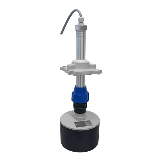
- Page 1 EasyTREK SCD-300 integrated ultrasonic level transmitter series for free flowing solids Manufacturer: NIVELCO Process Control Co. H-1043 Budapest, Dugonics u. 11. Phone: (36-1) 889-0100 Fax: (36-1) 889-0200 E-mail: sales@nivelco.com www.nivelco.com BKI16ATEX0020X ♦ scd3404a0600p_03 ♦ 1 / 36...
- Page 2 PRINCIPLES OF ULTRASONIC LEVEL MEASUREMENT Angle of repose: DIST=distance (measured) LEV= level calculated H-DIST) VOL= volume (calculated from LEV) 2 / 36 ♦ BKI16ATEX0020X ♦ scd3404a0600p_03...
-
Page 3: Table Of Contents
C O N T E N T S 1. INTRODUCTION................... 5 6. MAINTENANCE, REPAIR..............33 2. TECHICAL DATA ................. 7 7. STORAGE CONDITIONS ..............33 2.1.................... 7 ENERAL DATA 8. WARRANTY..................33 2.2..................... 7 PECIAL DATA 9. PARAMETER TABLE ................. 34 2.3. - Page 4 BKI16ATEX0020X ♦ scd3404a0600p_03 ♦ 4 / 36...
-
Page 5: Introduction
A Total beam angle of 5 at –3 dB is a feature of all NIVELCO’s ultrasonic sensors designed for the level measurement of free flowing solids. This uniquely narrow beam angle ensures reliable measurement in narrow silos with uneven side walls or sometimes even in the presence of dusting. - Page 6 HE FOLLOWING TYPES OF APPLICATIONS ARE POSSIBLE DEPENDING ON THE COMMUNICATION AND WHAT THE OUTPUT SIGNAL IS USED FOR Using the unit as a three - or four -wire current transmitter. Normally, we use the analogue (4…20 mA) output signal of the EasyTREK. The application parameters of the device are set through HART communication at installation (right after installation or in a laboratory, prior to installation).
-
Page 7: Techical Data
2. TECHICAL DATA 2.1. G ENERAL DATA Type SCD-3 SCD-3 -8 Ex Closed cell Polyurethane foam sensor face (PUR) Closed cell Polyurethane foam sensor face (PUR) Transducer material PP and Aluminum transducer housing and fitting Aluminum transducer housing and fitting ∼... -
Page 8: Accessories
2.3. A CCESSORIES Installation and Programming Manual Warranty Card Declaration of Conformity EView configuration software and description on CD CCESSORIES TO BE ORDERED Split flange (order code: SFA – 3 5) 2.4. O RDER CODES EasyTREK D – 3 – ANGE OUNTING UTPUT... -
Page 9: Dimensions
2.5. D IMENSIONS SCD-310- SCD-310- Ex SCD-330- SCD-340- SCD-330-8 Ex SCD-340-8 Ex 1" BSP 1" BSP 1" BSP 1" BSP Ø37 Ø37 Ø37 Ø37 Ø292 Ø148 Ø146 Ø294 SCD-33J- SCD-33J-8 Ex SCD-31J- SCD-31J-8 Ex SCD-34J- SCD-34J-8 Ex Ball-joint Housing (view from above) BKI16ATEX0020X ♦... -
Page 10: Installation
3. INSTALLATION LACEMENT To find the ideal position for the location of the EasyTREK level transmitter various considerations should be made.The transmitter should not be installed in the centre of the tank/silo when the tank roof is dome shaped or conical. The ideal position for the EasyTREK is on the r = (0.3 … 0.5) R (in case of cylindrical tank). Avoid that the 5°... - Page 11 When the entire tilting range of the aiming arm is required, the thickness of the roof can not exceed the values specified below. The EasyTREK can also be mounted on existing (manhole) covers, access lids or for instance on a steel structure lowered into a larger (ex.: 0.5 x 0.5 m) opening on the roof.
-
Page 12: Wiring
4. WIRING 4.1. W IRING CONDITIONS Brown Supply The transmitter is SELV supplied. In the case of DC supply the connection is independent of Green polarity. + HART Only SELV circuits can be switched on to the relay or the solid state output. Grey The house must be grounded to have noise protection;... - Page 13 Multiple SCD-300 transmitters connected to a MultiCONT process control unit Trial and laboratory programming of the SCD-300 transmitters Output current test Power is supplied from a common external source, the relays are not used. Grey EasyTREK DEVICES White MultiCONT 26 27 28 Brown SELV supply...
-
Page 14: Putting Into Operation, Adjusting, Programming
EFAULT PARAMETERS All the transducers get the same factory default parameters that can also be reset later if needed. Some of the most important parameters of the EasyTREK SCD-300 series can be found below. Measurement mode: level (LEV), Zero level is assigned to the maximum measuring distance (X... -
Page 15: Status Indication Signals In Measuring Mode
EView configuration software run on PC – by the NIVELCO made MultiCONT multichannel controller This instruction describes parameters and features behind them but does not deal with technical details for their selection and editing of their values. Compact Disk attached to the transmitter contains detailed information on the Eview configuration software (to install on PC) and its description. -
Page 16: Arameters Escription And Programming
5.4. P –D ARAMETERS ESCRIPTION AND PROGRAMMING 5.4.1. Measurement Configuration P00: - c b a Application/Engineering Units FACTORY DEAFAULT: 001 ATTENTION! Programming of this parameter will result in loading the factory default with the corresponding engineering units. Operating (measurement) mode Free flowing solids level measurement Engineering units (according to “c”) ( according to „c”) - Page 17 P01: - - 1 a Measurement Mode FACTORY DEAFAULT: 11 Values transmitted by HART protocol, current output and the switching points of the relays will be interpreted into the engineering units of the (measured or calculated) process value corresponding to the programmed measurement mode. On the other hand, the higher the “a” of the programmed parameter value the more (measured or calculated) process values can be transmitted through HART (e.g.
- Page 18 P02: - c b a Calculation units FACTORY DEAFAULT: 000 Temperature °C °F This table is interpreted according to P00(c), P01(a) and P02(c) and is irrelevant in case of percentage measurement ( P01(a)= 2 or 4 ) Volume Weight (set also P32 Metric Metric tone...
- Page 19 P05: - - - - Minimum measuring distance (Close-end blocking) FACTORY DEFAULT: automatic close end blocking (X as per the table) Basic feature of the ultrasound level meters is their not being able to measure next to the sensor surface. Within this range the measurement can not be interpreted, thus it should be avoided that material level get into this range.
- Page 20 P06: - - - - Far-end blocking FACTORY DEFAULT: 0 Far-end blocking is the range below the level set in parameter P06. Far-end blocking can be used to avoid disturbing effects of stirrers or heaters at the bottom of the tanks. When the unit detects echoes in this range it gives special signals.
-
Page 21: Current Value
5.4.2. Current value P08: - - - - Fixed output current FACTORY DEFAULT: 0 With this step the output current can be set as a fix value, selected between 3,8 mA and 20,5 mA. Output current will be fixed until the value of P08 is programmed back to 0 again. -
Page 22: Relay Output
5.4.3. Relay output P13: - - - a Relay functions FACTORY DEFAULT: 2 Relay functions Also to set: Level P14, P15 If the value selected for controlling the relay Keep at least 2 cm DIFFERENTIAL difference between P14 increases over P14 : relay energises LEVEL CONTROL Time and P15... -
Page 23: Measurement Optimalization
5.4.4. Measurement optimalization P20: - - - a Damping FACTORY DEFAULT: 7 This parameter can be used for reduction of unwanted fluctuation of the displayed value and the output. Granules Damping time [s] particle size >2-3 mm particle size < 1-2 mm None For test only Not recommended... - Page 24 P24: - - - a Target tracking speed FACTORY DEFAULT: 0 With this parameter the evaluation can be sped up at the expense of the accuracy. Tracking speed Remark Standard For most applications Fast For fast changing level For very special cases only, as this reduces the maximum measuring range to 50% of the nominal value! Special The measuring window (P25 and P33) is inactive and the EasyTREK will respond practically instantly to any target.
- Page 25 P28 - - - a Echo-loss handling FACTORY DEFAULT: 0 Echo-loss error Remark indication During short periods of echo-loss, both Eview and the analogue output will hold last value. The current output holds last value for twice as long as set in P20 before going to the "Error Indication Mode" set in P12. Error Code 2 Holding value HART...
- Page 26 P29 - - - - Blocking out of object FACTORY DEFAULT: 0 One object in the tank/silo disturbing measurement can be blocked out. Enter distance of the object from the transducer. Use the Echo Map (P70) to read out the precise distance of disturbing objects. P31: - - - - Sound velocity at 20°C (m/sec or ft/sec) FACTORY DEFAULT: Metric (P00: “EU”): 343.8 m/s, US (P00: “US”): 1128 ft/s...
- Page 27 ANUAL ECHO SELECTION Weak echo Disturbing echo from the surface Eg.: 5.2 m Eg.: 3.85 m Received signal amplitude (flight time) measuring window Transmitted DIST value (locked on the disturbing echo) (of the disturbing echo) Window signal (comp.) Setting: P33=4.00 (results in shifting the measuring window to 4 m) Window signal (comp.) Measuring Window finds the echo from the surface...
-
Page 28: Volume Measurement
5.4.5. Volume measurement P40: - - ba Tank / silo shape FACTORY DEFAULT: 00 Other parameters to be set Tank/silo shape Standing cylindrical tank shape: value of “b” as below bottom P40(b), P41 Standing cylindrical tank/silo with conical bottom P41, P43, P44 Standing rectangular tank/silo (with chute P41, P42, P43, P44, P45 Lying cylindrical tank shape: value of “b”... -
Page 29: Linearisation
5.4.6. Linearisation P47: - - - a Linearisation FACTORY DEFAULT: 0 Linearisation is the method of assigning requested (calibrated or calculated) level, volume or flow to values measured by the transmitter. It can be used for instance if the sound velocity is not known (LEVEL LEVEL) or in the case of tank with other shape than under 5.4.5. (LEVEL VOLUME). -
Page 30: Informational Parameters
5.4.7. Informational parameters P60: - - - - Overall operating hours of the unit (h) P61: - - - - Time elapsed since last switch-on (h) P62: - - - - Operating hours of the relay (h) P63: - - - - Number of switching cycles of the relay (h) P64: - - - - Actual temperature of the transducer (°C/°F) -
Page 31: Test Parameters
5.4.8. Test parameters P96: - - - - Checksum P97: - - - - Software code (Read only parameter) P98: - - - - Hardware code (Read only parameter) P99: - - - - Access lock by secret code The purpose of this feature is to provide protection against accidental programming of parameters or by a person. not entitled. The secret code can be any value other than 0000. -
Page 32: Error Codes
5.4.9. Error codes Error Error description Causes and actions to be done Code Memory error Contact local agent No Echo Bad reflection from the surface, reflection not directed towards the sensor, due to Echo loss or echo too weak to evaluate dusting excessive sound absorption. -
Page 33: Maintenance, Repair
Repairs during or beyond the guarantee period are carried out solely by the manufacturer. 7. STORAGE CONDITIONS Ambient temperature: -30 ... +60°C Relative humidity: max. 98 % 8. WARRANTY NIVELCO provides warranty of 3 (three) years in compliance with details described in the Warranty Card. BKI16ATEX0020X ♦ scd3404a0600p_03 ♦ 33 / 36... - Page 34 9. PARAMETER TABLE Par. Page Description Value Par. Page Description Value d c b a d c b a Application/Engineering Units Echo loss indication Measurement Mode Blocking out of disturbing object Calculation units – Values displayed - Rounding Sound velocity in different gases Maximum Measuring Distance Specific gravity Minimum Measuring Distance...
- Page 35 Page Description Value Description Value Par. Par. Page d c b a d c b a – TOT2 volume flow totalised – – – – – – Overall operating hours of the unit – Time elapsed after last switch-on – Operating hours of the relay –...
- Page 36 September, 2016 Nivelco reserves the right to change technical data without notice! 36 / 36 ♦ BKI16ATEX0020X ♦ scd3404a0600p_03...
Need help?
Do you have a question about the EasyTREK SCD-300 Series and is the answer not in the manual?
Questions and answers