Table of Contents
Advertisement
Quick Links
Advertisement
Table of Contents

Related Manuals for NIVELCO EchoTREK SG-300 series


Summary of Contents for NIVELCO EchoTREK SG-300 series
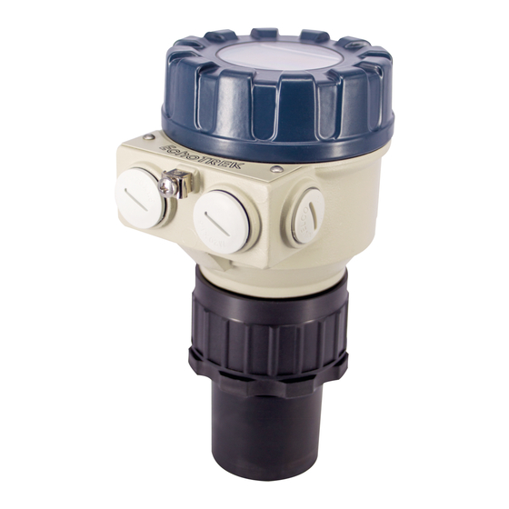
- Page 1 EchoTREK SE/SG-300 series two-wire compact ultrasonic level transmitters Manufacturer NIVELCO Process Control Co. H-1043 Budapest, Dugonics u. 11. Phone: (36-1) 889-0100 Fax: (36-1) 889-0200 E-mail: sales@nivelco.com www.nivelco.com BKI 03 ATEX 027X ♦ sea3802a0600p_03 ♦ 60/1...
- Page 2 BASIC CONCEPTS AND ELEMENTS OF THE ULTRASONIC MEASUREMENT Close end blocking (programmed value DIST= distance (measured) Programmed measurement range of the application LEV= level calculated; H - DIST) → VOL= volume (calculated from DIST LEV) Far end blocking 60/2 ♦ BKI 03 ATEX 027X ♦ sea3802a0600p_03...
-
Page 3: Table Of Contents
CONTENTS 1. INTRODUCTION..................5 6. PARAMETERS – DESCRIPTIONS AND PROGRAMMING....26 6.1 M ............26 EASUREMENT ONFIGURATION 2. ORDER CODES..................6 6.2 C ................32 URRENT UTPUT 6.3 R ................. 33 ELAY UTPUT 3. TECHNICAL DATA.................7 6.4 D ................33 IGITAL OUTPUT 6.5 M ............ - Page 4 60/4 ♦ BKI 03 ATEX 027X ♦ sea3802a0600p_03...
-
Page 5: Introduction
1. INTRODUCTION Application A Total beam angle of 5 -7 at –3 dB as is featured by most of Nivelco’s SenSonic transducers ensuring a reliable measurement in narrow silos with The EchoTREK compact ultrasonic level transmitters from NIVELCO are an uneven side walls as well as in process tanks with various protruding objects. -
Page 6: Order Codes
2. ORDER CODES Note: not all combinations are possible EchoTREK S RANSDUCER EASURING OUNTING UTPUT OUSING ANGE Transmitter PP/Aluminium 12; 15 m BSP thread 4 … 20 mA / LOGGER Transmitter with PP + foam / Aluminum 7; 10 m NPT thread 4 …... -
Page 7: Technical Data
Aluminium housing –30 °C ... +70 °C with display –25 °C… + 60 °C Plastic housing –20 °C ... +70 °C with display –20 °C… + 60 °C For pressures below 1 bar representative of Nivelco should be consulted. Under optimal circumstances of reflection and stabilised transducer temperature. - Page 8 PECIAL DATA OF THE TWO WIRE WITH TRANSDUCERS EchoTREK PVDF ALSO APPLY FOR X MODELS SE -38 - SE -39 SE -37 SE -36 SE -34 SG -38 - SG -37 - SG -36 - SG -34 - SG -39 Transducer material PP or PVDF PP or PVDF...
- Page 9 Dimensions of the two-wire EchoTREK EchoTREK S -39 - / PP, PVDF, PTFE EchoTREK S -3 8- / PP, PVDF, PTFE EchoTREK S -37 - / PP, PVDF, PTFE 2 x M20x1.5 2 x M20x1.5 2 x M20x1.5 2 x 1/2" NPT 2 x 1/2"...
- Page 10 EchoTREK S S-36 - / SS316 Ti Cover 2 x M20x1.5 1/2" Display unit Electronics DIN DN80 PN16 ANSI 3" 150 psi EchoTREK S S-34 - / SS316 Ti Housing 2 x M20x1.5 1/2" Transducer DIN DN125 PN16 ANSI 5" 150 psi 60/10 ♦...
-
Page 11: Accessories
3.3.1 S Based on the observations & needs of our customers NIVELCO constantly improves and revises the operating software of the device. The software can be upgraded with the help of the IrDA communication port of the SAP-200 or an ELink (USB) communication adapter plugged into the SAP-200 slot. For more information about software updates please contact Nivelco. -
Page 12: Installation
4. INSTALLATION IQUID EVEL EASUREMENT 4.1 L POSITION The optimal position of the EchoTREK is on the radius r = (0.3 … 0.5) R of the (cylindrical) tank / silo. (Take also sonic cone on page 1 into consideration.) SENSOR ALIGNMENT TEMPERATURE The sensor face has to be parallel to Make sure that the transmitter will... - Page 13 OBSTACLES STAND-OFF PIPE Make sure that no in-flow path or objects The structure of the stand off pipe should be rigid; the inner rim where the ultrasonic beam (e.g. cooling pipes, ladders, bracing leaves the pipe should be rounded. members, thermometers, etc.) or no tank D min wall of the ragged surface protrude into - 39...
-
Page 14: Open Channel Flow Measurement
Install the device in a place defined by the characteristics of the metering channel along the longitudinal axis of the flume or weir. In case of Parshall flumes supplied by NIVELCO the location of the sensor is marked. In some cases foam may develop on the surface. Make sure that the surface, opposite to the sensor remain free of foam for proper sound reflection. -
Page 15: Programming
5. PROGRAMMING The EchoTrek can be programmed by the following two ways: Programming without Display Module see 5.1. Assignment of the levels to the 4 and 20 mA current output, error indication by the analogue signal and damping can be set. With the SAP-200 Display Module, see 5.2. -
Page 16: Programming Without Displaym
ROGRAMMING WITHOUT ISPLAY ODULE 5.1 P Programming is only possible if the EchoTREK is in Level Measuring Mode and receives valid echo i.e. “VALID” LED is lit! The following can be programmed without display module Assignment of the 4 mA to a required e.g. min. level / max. distance Assignment of the 20 mA to a required e.g. - Page 17 Maximum level (100%, full tank) assignment to 20 mA Action Led state following the action 1) Check for a valid ECHO Valid ECHO, transmitter programmable 2) Press NEXT button steadily EchoTREK in programming mode 20 mA as signed to the distance 3) Press DOWN button steadily (see picture)
- Page 18 Damping time setting (Check for a valid echo as above) Action Led state following the action 1) Press ENTER button steadily EchoTREK in programming mode – 10 sec 2) Press any of the NEXT – 30 sec – 60 sec DOWN buttons steadily 3) Release buttons...
-
Page 19: Isplay Module
5.2 P ROGRAMMING WITH THE SAP-200 D ISPLAY ODULE The EchoTREK should be adjusted to the process by programming the parameters. The SAP-200 Display Module can be used to display the parameters during programming and measurement values during measurement. The SAP-200 supports two separately accessible programming modes representing 2-layers of programming complexity, depending on user choice. PLUG-IN DISPLAY MODULE FULL QUICKSET... -
Page 20: Sap-200 Display Module
5.2.1 SAP-200 Display Module Symbols used on the LCD: Symbols used on the frame: DIST – Distance (measuring) mode M – Metric system LEV – Level (measuring) mode US – US calculation system VOL – Volume (measuring) mode FLOW – Open channel (flow metering) mode PROG - Programming mode (device under programming) COM –... -
Page 21: Indications Of The Sap-200 And Led Status
Enter into or quit programming modes Basic steps while parameter address is blinking Basic steps while parameter value is blinking Return to default* Display default value * cancellation immediately active * LOAD readout ** CANCEL readout GET LEVEL function Special function used only in level and distance measurement modes + DOWN Notes: If after pressing ENTER... -
Page 22: Quickset
SAP-200 indications The following process values can be displayed Depending on the measurement one of the below symbols will lit and the process value Volume / Flow – if programmed so (Vol/Flow) displayed (see P01 chapter 6.1). Engineering Level – if programmed so units will be indicated directly (°C, °F and mA) Distance –... - Page 23 Keys Function + DOWN (press for min 3 secs!) Enter or exit QUICKSET programming mode ENTER , DOWN , NEXT Increase/decrease and move left the blinking digit + DOWN “GET LEVEL" - display actual level measured by the EchoTREK Save readout and step to the next screen ENTER NEXT + UP...
-
Page 24: Full Parameter Access
Screens Actions 20 mA xxxx – level value assigned to 20 mA current output Manual: set level value (Use UP / DOWN / NEXT keys) and save it (by ENTER 20 :xxxx Automatic: use the “GET LEVEL” function (UP + DOWN ) to obtain actual measured value with level in tank or a fixed target, i.e. - Page 25 Measuring is going on during programming in accordance with the old parameter set. New parameter set will be valid after returning to the Measurement to the Programming Mode. Steps and indications of the Full Parameter Access programming mode pressing Keys while Parameter Address is blinking while Parameter Value is blinking Save the modification of the Parameter Value and return...
-
Page 26: Parameters - Descriptions And Programming
6. PARAMETERS – DESCRIPTIONS AND PROGRAMMING EASUREMENT ONFIGURATION 6.1 M P00: - cba Application/Engineering Units Programming of this parameter will result in loading the factory default with the corresponding engineering units. Operating (measurement) mode Liquid level measurement Engineering units (according to “c”) Attention: mind the sequence! When programming this parameter the Metric... - Page 27 P01: - ba Measurement Mode – Bargraph Parameter value „a” will determine the basic measurement value that will be displayed and proportional with the current output. Depending on the value of “a” process values as listed in the 3d column can also be displayed by pressing NEXT .
- Page 28 P03: - - - a Values displayed - Rounding It is important to keep in mind that the instrument is measuring distance as basic quantity. Measured Distance Resolution The resolution depending on the distance can be considered as a kind of rounding that will be contained in all further value (of level, volume or volume –...
- Page 29 Maximum Distance to be Measured (H) The maximum distance to be measured is the greatest distance between the surface of the transducer and the level to be measured. This is the only parameter that has to be programmed for each application other than distance (however to avoid disturbing effect of possible multiple echos it is suggested to do this in distance measurement applications too).
- Page 30 P05: Minimum measuring distance (Dead zone- Close-end blocking) The EchoTREK will not accept any echo within the blocking distance set here. Automatic Close-end-blocking (Automatic Dead Band control) By using the factory default value, the unit will automatically set the smallest possible close-end-blocking distance i.e. the dead band. Manual close-end-blocking Manual close-end-blocking should be used for example to block out the echo originating from the bottom rim of a stand-off pipe or from any object protruding into the ultrasonic cone near to the transmitter.
- Page 31 P06: Far end blocking Far end blocking is used to neglect incorrect level/volume readings and output actions below a pre-set level programmed in P06. A). Level measurement The far-end blocking can be used to avoid disturbing effect of stirrer or heaters at the bottom of the tanks. If the level of the medium sinks below the blocked out range: "SUB 0"...
-
Page 32: Current Output
URRENT UTPUT 6.2 C P10: Value (of distance, level, volume or flow) assigned to 4 mA current output P11: Value (of distance, level, volume or flow) assigned to 20 mA current output Values are interpreted according to P01(a). Please note that in case of programming for (LEV or VOL) % measurement the min and max value has to be entered in the relevant engineering units of LEV (m, ft) or VOL (m , ft Assignment can be made so that the proportion between the change of the (measured or calculated) process value and the change of the current... -
Page 33: Relay Output
6.3 R ELAY UTPUT P13: - - - a Relay function Relay function Also set DIFFERENTIAL LEVEL CONTROL P14, P15 Level (Hysteresis control) There is a need to set (in level Relay is energised if the measured or calculated value min 20mm) hysteresis between Time exceeds the value set in P14 Relay is de-energised if... -
Page 34: Measurement Optimisation
EASUREMENT PTIMISATION 6.5 M P20: - - - a Damping This parameter can be used to reduce unwanted fluctuation of the display and output. Damping LIQUIDS time None/moderate Heavy/dense fume or (seconds) fume or waves turbulent waves no filter applicable not recommended recommended applicable... - Page 35 P25: - - - a Selection of Echo within the measuring window A so-called measuring window is formed around the echo signal. The position of this measuring window determines the flight time for calculation of the distance to the target. (the picture below can be seen on the test oscilloscope) Received Echo 2.
- Page 36 P28: - - - a Echo loss indication Echo loss indication Remark During echo-loss, display and analogue output will hold last value. If the echo-loss prevails for 10 sec plus the time period set in P20 (damping time), the reading on the display will change to "no Echo"...
- Page 37 P29: Blocking out of disturbing object One fixed object in the tank, disturbing the measurement, can be blocked out. Enter distance of the object from the transducer. Use the Echo Map (P70) to read out the precise distance of disturbing objects. FACTORY DEFAULT: 0 P31: Sound velocity at 20°C (m/sec or ft/sec depending on P00(c) )
-
Page 38: Data Logger
ATA LOGGER 6.6 D The logger of the device can store 12288 events. The registry is in a non-volatile (FLASH) memory, so the registry will retain its contents even in case of a power failure. The on-board clock of the device is protected against short power-outs, and keeps working for at least 15 days after the device is switched off. - Page 39 P34: - cba Logging mode Operating mode Parameters to be programmed No logging Linear logging P35 – interval (minute) Event-controlled logging when the primary value changes P35 – absolute value of variation Event-controlled logging when primary value changes P35 – variation in % Event-controlled logging when the primary value gets out P35, P36 –...
- Page 40 P35-36: Log value 1 and log value 2 P34a Operating mode Function of P35 and P36 No logging Linear logging P35 = 0 One entry after every measurement cycle. P35 <> 0 Logging interval (minutes) Value is indifferent Event-controlled logging when the Absolute value of the change in the primary measured value primary value changes (according to P01a)
-
Page 41: Reading Data Out From The Logger
HART communication, but because of the slow speed of HART, it takes several hours. To access the data content the use of NIVELCO’s DataScope program is recommended. During the high-speed communication with ELink or SAP-200 the device sets the output current to 22 mA. -
Page 42: Volume Measurement
OLUME EASUREMENT 6.7 V P40: - - ba Tank shape Tank shape Also to be set Standing cylindrical tank shape (value of “b” as below) P40 (b), P41 Attention! Standing cylindrical tank with conical bottom P41, P43, P44 The value „a” determining the shape of the tank should be Standing rectangular tank (with chute) P41, P42, (P43, P44, P45) -
Page 43: Volume Flow Measuring
6.8 V OLUME EASURING P40: - - ba Devices, formula, data Devices, formula, data Also to be set Type Calculation formula Qmin [l/s] Qmax [l/s] “P” [cm] GPA-1P1 Q[l/s]= 60.87*h 1.552 0.26 5.38 GPA-1P2 Q[l/s]= 119.7*h 1.553 0.52 13.3 1.555 GPA-1P3 Q[l/s]= 178.4*h 0.78... - Page 44 P41-45: Flume/weir dimensions FACTORY DEFAULT: P40= 00 Nivelco Parshall flumes (GPA1P1 … GPA-1P9) For further details see the Manual of the Parshall flume EchoTREK EchoTREK P40= 09 General Parshall flume 0.305 < P42(width) <2.44 ⋅ 2.5 < P42 EchoTREK /s]= K*P42*h P42[m] 3.05...
- Page 45 P40= 10 Palmer-Bowlus (D/2) flume /s]= f(h1/P41)*P41 where h1[m]= h+(P41/10) D/10 P40= 11 Palmer-Bowlus (D/3) flume /s]= f(h1/P41)*P41 where h1[m]= h+(P41/10) D/10 P40= 12 Palmer-Bowlus (Rectangular) flume /s]= C*P42*h where C= f(P41/P42) D/10 BKI 03 ATEX 027X ♦ sea3802a0600p_03 ♦ 60/45...
- Page 46 15cm P40= 13 Khafagi Venturi flume /s]= P42*1.744*h + 0.091*h EchoTREK EchoTREK P40= 14 P40=14 Bottom step weir 0.0005 < Q[m /s] < 1 0.3 < P42[m] < 15 0.1 < h[m] < 10 /s]= 5.073*P42*h Accuracy: 10% P40= 15 P40=15 Suppressed rectangular or BAZIN weir 0.001 <...
- Page 47 P40= 16 P40=16 Trapezoidal weir 0.0032 < Q[m3/s] < 82 20 < P41[°] < 100 0.5 < P42[m] < 15 0.1 < h[m] < 2 2.47 Q[m3/s]= 1.772*P42*h1.5+1.320*tg(P41/2)*h Accuracy: 5% P40= 17 P40=17 Special Trapezoidal (4:1) weir 0.0018 < Q[m3/s] < 50 0.3 <...
- Page 48 P40= 19 P40=19 THOMSON (90°-notch) weir 0.0002 < Q[m3/s] < 1 0.05 < h[m] < 1 2.47 Q[m3/s]= 1.320*h Accuracy: 3% P40= 20 P40=20 Circular weir 0.0003 < Q[m /s] < 25 0.02 < h[m] < 2 /s]= m*b*D m= 0.555+0.418h/P41+(P41/(0.11*h)) ±...
-
Page 49: 32-Point Linearisation
OINT INEARISATION 6.9 32-P P47: - - - a Linearisation Linearisation is the method of assigning requested (calibrated or calculated) level, volume or flow to values measured by the transmitter. It can be used for instance if the sound velocity is not known (LEVEL⇒LEVEL) or in the case of tank with other shape than under 6.4 or open channel other than under 6.5 (LEVEL ⇒... -
Page 50: Informational Parameters
Conditions of correct programming of the data pairs Left column “L” Right column “r” L(1)= 0 r(1) L(i) r(i) L(j) r(j) The table must always start with: L(1)= 0 and r(1)= value (assigned to 0 level) The table must be ended either with the 32 data pair i.e. - Page 51 P70: Number of Echoes / Echo Map Number of echos yy : xxxx yy : xxxx EchoTREK is monitoring the echo 70 : _ _ XX conditions. (AMPLITUDE) (DISTANCE) Entering this parameter will save the actual echo map. yy Serial number of the echo Number, distance and amplitude of these xx value of...
-
Page 52: Additional Parameters Of The Flow
DDITIONAL ARAMETERS OF THE ETERING 6.11 A P76: Head of flow (LEV) The Headwater value can be checked here. This is the “h” value in the formula for flow calculation. P77: TOT1 volume flow totaliser (resetable) P78: TOT2 volume flow totaliser (non-resetable) Resetting TOT1 totaliser: 1). -
Page 53: Test Parameters
ARAMETERS 6.13 T P80: Current output test (mA) Going to this parameter, the actual current output (corresponding to the measured process value) will be displayed. By pressing ENTER (now blinking) current value can be set for any value between 3,9 and 20.5 mA. The current output has to show the same value which can be checked by an ampere meter, according to the description under 4.4. -
Page 54: Simulation
IMULATION 6.14 S This function enables the user to test the settings of the outputs. The EchoTREK can simulate the static or continuous change of level according to the simulation cycle time, high level and low level set in P85, P86 and P87. (The simulation levels must be within the programmed measuring range set in P04 and P05.) After selecting simulation type in P85 and setting simulation values Measurement Mode has to be re-entered. -
Page 55: Error Codes
7. ERROR CODES Error Error description Causes and solutions Code Memory error Contact local agent No echo received (no reflection) No Echo Echo loss See Action 5 and 6 Hardware error Contact local agent Display overflow Check settings Sensor error or improper installation/mounting, level in Verify sensor for correct operation and check for correct mounting the dead band according to the User’s Manual... -
Page 56: Parameter Table
8. PARAMETER TABLE Par. Page Description Value Par. Page Description Value d c b a d c b a Application/Engineering Units Echo loss indication Measurement Mode Blocking out of disturbing object Calculation units N.A. Rounding Sound velocity in different gases Maximum Measuring Distance Specific gravity Minimum Measuring Distance... - Page 57 Par. Page Description Value Par. Page Description Value N.A. TOT2 volume flow totaliser N.A. N.A. N.A. Current generator test N.A. Relay test Overall operating hours of the unit N.A. Time elapsed after last switch-on N.A. Operating hours of the relay Simulation mode Number of switching cycles of the relay Simulation cycle time...
-
Page 58: Sound Velocities In Different Gases
9. SOUND VELOCITIES IN DIFFERENT GASES The following table contains the sound velocity of various gases measured at. Gases Sound Velocity (m/s) Gases Sound Velocity (m/s) Acetaldehyde 252.8 Ethylene 329.4 Acetylene 340.8 Helium 994.5 Ammonia 429.9 Hydrogen sulphide 321.1 Argon 319.1 Methane 445.5... - Page 59 BKI 03 ATEX 027X ♦ sea3802a0600p_03 ♦ 60/59...
- Page 60 June, 2011 Nivelco reserves the right to change technical data without notice! 60/60 ♦ BKI 03 ATEX 027X ♦ sea3802a0600p_03...
Need help?
Do you have a question about the EchoTREK SG-300 series and is the answer not in the manual?
Questions and answers