
Related Manuals for Hach LANGE LICO 500


Summary of Contents for Hach LANGE LICO 500
- Page 1 DOC027.53.00792 LICO 500 USER MANUAL March 2007 Edition 1 ©Hach Lange GmbH, 2007. All rights reserved. Printed in Germany. sd/sk...
-
Page 3: Table Of Contents
Table of contents Section 1 Specifications ............................5 Section 2 General Information ..........................7 2.1 Safety information .............................. 7 2.1.1 Use of hazard information ......................... 7 2.1.2 Precautionary labels ..........................7 2.1.3 Chemical and Biological Safety ........................ 7 2.2 Overview of product ............................8 Section 3 Installation ............................. - Page 4 Table of Contents 5.5 Color measurement ............................41 5.5.1 Take a color measurement ........................42 5.5.1.1 Touch-sensitive areas on the measurement window ..............43 5.5.1.2 Parameter setup options ......................44 5.5.1.3 Change the color scale after a measurement ................45 5.5.1.4 Change the measuring range after a measurement ..............
- Page 5 Table of Contents Section 7 Maintenance ............................85 7.1 Cleaning requirements ............................. 85 7.1.1 Housing and cell compartment ....................... 85 7.1.2 Display ..............................85 7.1.3 Cuvettes/sample cells ..........................85 7.2 Lamp replacement ............................86 7.3 Filter pad maintenance ............................ 88 7.3.1 Filter pad replacement ..........................
-
Page 7: Section 1 Specifications
Section 1 Specifications Specifications are subject to change without notice. Performance specifications Color measurement, color difference measurement, Absorbance and Operating mode Concentration All color values calculated for standard illuminant C of ASTM E 308 and a Colorimetric evaluation 2°standard observer. Source lamp Gas-filled Tungsten (visible) Wavelength range... -
Page 9: Section 2 General Information
Section 2 General Information 2.1 Safety information Please read this entire manual before unpacking, setting up or operating this equipment. Pay attention to all danger, warning and caution statements. Failure to do so could result in serious injury to the operator or damage to the equipment. To make sure that the protection provided by this equipment is not impaired, do not use or install this equipment in any manner other than that specified in this manual. -
Page 10: Overview Of Product
General Information Normal operation of this instrument may involve the use of hazardous chemicals or biologically harmful samples. • The user must observe all cautionary information printed on the original solution containers and safety data sheet prior to their use. •... -
Page 11: Section 3 Installation
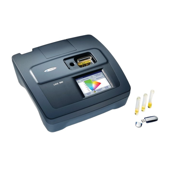
Section 3 Installation WARNING Electrical and Fire Hazards. Use only the provided power supply. Only qualified personnel should conduct the tasks described in this section of the manual. 3.1 Unpack the instrument The LICO 500 comes packaged with the following items: •... -
Page 12: Power Connections
Installation 3.3 Power connections Install the correct adapter plug on the supplied external power supply (Figure 1). Slide the adapter on until it "clicks" into position. Plug the external power supply cord into the connector on the back panel of the instrument, then plug the supply into a power outlet (100–240 V~ / 50–60 Hz). -
Page 13: Interfaces
A USB memory stick is used to update instrument software. The USB Type B interface is used for communications with a PC. The optional Hach Data Trans software (see Section 9 on page must be installed on the PC for this use. -
Page 14: Cell Compartments And Cell Adapter
Installation 3.5 Cell compartments and cell adapter 3.5.1 Cell compartments and adapter The LICO 500 has two cell compartments (Figure 3). Only one cuvette/sample cell type at a time can be used for a measurement. Cell compartment #1 • 11-mm round cuvettes/sample cells For measurements with 11mm round cuvettes/sample cells in cell compartment #1 insert the adapter Z into cell compartment Cell compartment #2... -
Page 15: Installation Of The Cell Adapter
Installation Figure 4 Cell adapter Z Adapter Z: 10 mm square cell adapter 3.5.2 Installation of the cell adapter 1. Open the cell compartment. 2. Insert the adapter for measurements with the round cuvette/sample cell (11 mm) and/or 10 mm square cuvette/sample cell so the arrow on top of the adapter points to the left (Figure... -
Page 16: Beam Path
Installation 3.6 Beam path Figure 5 shows the beam path of the LICO 500. Figure 5 Beam path Tungsten lamp Filter wheel Entrance slit 10 Splitter mirror Heat-protection glass 11 Reference-element Grating 12 Cell compartment 13 Lens Chopper 14 Measurement element Exit slit 15 Cell compartment #1 Lens... -
Page 17: Section 4 Start Up
Section 4 Start Up 4.1 Power the instrument on and off 1. Plug external power supply into an electrical outlet. 2. Press the power switch on the back of the instrument to initialize power. Note: Do not turn the instrument off and on in rapid succession. Always 20 seconds wait about before turning the instrument on again, otherwise... -
Page 18: Characteristics In Continuous Operation
Start Up The Main Menu is displayed when diagnostics are completed. See section 5.1.3 Main Menu on page 18 for a detailed description. 4.4 Characteristics in continuous operation After a continuous operating time of more than 24 hour without switching off the instrument we recommend to perform a new calibration with a distilled water cuvette/sample cell. -
Page 19: Section 5 Standard Operations
Section 5 Standard Operations 5.1 Overview 5.1.1 Tips for the use of the touch screen The entire screen is touch-activated. To make a selection, press the screen with a fingernail, fingertip, pencil eraser or a stylus. Do not press the screen with a sharp object, such as the tip of a ball point pen. -
Page 20: Main Menu
Standard Operations 5.1.3 Main Menu A variety of modes may be selected from the Main Menu. Table 2 briefly describes each menu option. Table 2 Main Menu options Option Function The COLOR MEASUREMENT mode is used to determine visual color values like Hazen, Color Measurement Gardner, Saybolt as well as three-dimentional absolute colorimetric values like CIE Lab, Hunter Lab or European Pharmacopoeia skale. -
Page 21: Instrument Setup Mode
Standard Operations 5.2 Instrument Setup mode 1. Select Instrument Setup in the Main Menu. A selection of configuration options appear. 5.2.1 Operator ID Use this option to enter up to 30 sets of operator initials (up to five characters each). Also the color can assigned for each Operator ID. This feature helps record which operator measured each sample. -
Page 22: Sample Id
Standard Operations Each operator is able to configure his own set of color scales for display and printout independent of the settings or configuration of other operators. When the operator ID is changed from A to B the color scales for the display and printout also change. - Page 23 Standard Operations 1. Press Sample ID in the Instrument Setup. 2. Press New to enter a new Sample ID. 3. Use the alphanumeric keypad to enter a new Sample ID. Note: If a USB Barcode handset scanner ( see Section 9 on page is connected, Sample IDs can also be scanned.
-
Page 24: Date And Time
Standard Operations 5.2.3 Date and time 1. Press Date & Time in the Instrument Setup. 2. The date and time are subdivided over a number of fields. Press the appropriate field and use the arrow keys to change the value. 3. - Page 25 Standard Operations • If the instrument is not used during a longer period (1–12 hours). • If the instrument will never be switched off. 1. Press Lamp Control in the Instrument Setup. 2. Select On to switch on the Lamp. 3.
-
Page 26: Pc And Printer
This USB interface is only intended for the LICO 500 to PC connection (with installation of the USB (Type B) HACH Data Trans Software). USB (Type A) This USB port can be used to connect a printer, a USB memory stick and keyboard. - Page 27 Standard Operations Printer Setup: • Resolution: Font size • Paper: Paper size Note: If an optional Thermal Printer is connected, the function "Auto Send" on/off is available. 3. Select Auto-Send: On to send all measured data automatically to the Thermal printer. Note: The option Auto-Send is not available for any other printer (e.g.
-
Page 28: Pc Setup
Standard Operations 6. Press Paper to select the paper size. Select between • Letter • Legal • Executive • 7. Press OK to confirm. Note: Press OK again to return to the Instrument Setup menu. 5.2.6.2 PC setup 1. Press PC. 2. -
Page 29: Print Data
Standard Operations 5.2.6.3 Print data 1. Press Recall Data in the Main Menu. 2. Select the data source, where the data to be printed are stored. 3. A list is displayed. Data can be filtered. For more information 5.3.1.2 Recall stored data from the color log or the data log on page 4. -
Page 30: Password
Standard Operations 5.2.7 Password The Password menu contains a variety of security settings to control access to various functions. For example, prevent unauthorized changes to stored programs or instrument configurations. 1. Press Password in the Instrument Setup menu. 2. In order to highlight the Security List assign a password. Press Set Password. -
Page 31: Deactivate A Password
Standard Operations 5. Highlight the desired functions to control. 6. Confirm the Security List with OK to return to the Password menu. 7. Press On to highlight the new settings of the Security List. 8. Enter the new Password again to confirm. 9. -
Page 32: Select Color
Standard Operations 5.2.8 Select color Select one of the four preset color palettes in the Select Color menu. 1. Press Select color in the Instrument Setup. A color chart list will appear. 2. Select a color category to highlight the color for the display background. -
Page 33: Store, Recall, Send And Delete Data
Standard Operations 5.3 Store, recall, send and delete data The data log of the instrument is seperated in 4 segments: Color Log, Wavelength Scan, Time Course and Data Log. The Color Log will store up to 500 color measurments taken in the Color Measurements and Color Difference Measurement modes. - Page 34 Standard Operations 4. The function Filter Settings is used to search for specific items. 5. Highlight On to turn on the filters to select data by • Sample ID • Operator ID • Start Date • Color Scale or any combination of the four. 6.
-
Page 35: Send Data From The Color Log Or The Data Log
Standard Operations 13. Highlight On to change the Upper Control Limit and the Lower Control Limit. 14. The middle Button represents the measuring points for the change-over. 5.3.1.3 Send data from the color log or the data log Data is sent from the data log as CSV (Comma Separated Value) files through a USB memory stick to a file named DATALOG. - Page 36 To send measurement data to a PC: The optional HACH Data Trans software must be installed on the PC for the subsequent to process for measurement data. 1. Press PC & Printer in the Instrument Setup.
-
Page 37: Delete Stored Data From The Color Log Or The Data Log
Standard Operations 5.3.1.4 Delete stored data from the color log or the data log 1. Press Recall Data in the Main Menu. 2. Press Color Log or Data Log, then Options>Delete. 3. Highlight Single Point or Filtered data or All data and press OK to confirm. -
Page 38: Store, Recall, Send And Delete Data From Wavelength Scan And Time Course
Standard Operations 5.3.2 Store, recall, send and delete data from wavelength scan and time course The instrument can store 20 Wavelength Scans and 20 Time Course Data sets.The data can be stored manually at the user's discretion after viewing the data. 5.3.2.1 Data storage from wavelength scan or time course 1. -
Page 39: Send Data From Wavelength Scan Or Time Course
1. Press Recall Data in the Main Menu and then Wavelength Scan or Time Course. 2. Press Options and then the PC & Printer icon to send the data to a USB memory stick, to a printer or to a PC with Hach Data Trans. - Page 40 Standard Operations • When a printer is connected, select how to send the data to the printer (graph, table or both graph and table). • When a USB memory stick is connected, the files will be automatically sent as CSV files (Comma Separated Value) to a file ”WLData“...
-
Page 41: Delete Stored Data From Wavelength Scan Or Time Course
Standard Operations 5.3.2.4 Delete stored data from wavelength scan or time course 1. Press Recall Data from the Main Menu and then Wavelength Scan or Time Course or Options>More>Recall Data. A listing of the stored data is displayed. 2. Highlight any data to delete. 3. -
Page 42: Sampling And Sample Preparation
Standard Operations 5.4 Sampling and sample preparation Take a representative sample from the product you want to measure in accordance with DIN EN ISO 15528 (or ASTM D3925-02). If the material shows any visual haziness, remove the haze by either filtration, centrifugation, heating, ultrasonic treatment or suitable means. -
Page 43: Color Measurement
Standard Operations 5.5 Color measurement Proper sample preparation is extremely important for accurate color measurement. To make sure an accurate measurement is taken, refer to the following sample preparation guidelines: • Always clean the glass cuvettes/sample cells immediately after use. •... -
Page 44: Take A Color Measurement
Standard Operations 5.5.1 Take a color measurement 1. Press Color Measurement. 2. Insert a cuvette/sample cell with distilled water to calibrate. Important Note: Carried out the calibration always very carefully, as a faulty calibration can cause inaccurate results to be obtained. 3. -
Page 45: Touch-Sensitive Areas On The Measurement Window
Standard Operations 5. Insert the sample cuvette/cell. 6. The result of the color calculation is displayed. Note: The control bar displayed on the right of the displayed result shows the relationship of the measurement result to the measuring range. 7. For the next measurement, remove the cuvette/sample cell and insert the next sample cuvette/cell or press Measure to measure the same sample again. -
Page 46: Parameter Setup Options
Standard Operations 5.5.1.2 Parameter setup options Press Option for Parameter Setup. Table 4 Stored programs options Options Description More For further Options With the setting, all measurement data are stored automatically. With the STORE ON STORE OFF Store: On setting, no measurement data are stored. Send Data To send data to a printer, computer or USB memory stick (Type A) Color Scale... -
Page 47: Change The Color Scale After A Measurement
Standard Operations 5.5.1.3 Change the color scale after a measurement 1. Press the touch-sensitive area 3, e.g. Color Value Hazen. 2. A list of all color scales is displayed. 3. Select the required scale. 4. Press OK to confirm. 5. The current result of the actual reading and all further measurements will be displayed in the selected color scale. -
Page 48: Change The Measuring Range After A Measurement
Standard Operations 5.5.1.4 Change the measuring range after a measurement 1. Press the upper or lower limit of the bar graph (touch-sensitive area 5 or 6). 2. Enter the new limit and press OK to confirm. Note: It is only possible to change the limits inside the measuring range of the color scale. - Page 49 Standard Operations The .ΔL*,.Δa*and .Δb* values are the numerical differences between the L*,a* and b* values of the sample and those of the displayed PHARMA color solution. The measurements can be carried out with cuvettes/sample cells with path lengths of 10 mm,11 mm or 50 mm.
- Page 50 Standard Operations 10. Graph offers a visualisation of the matching result in the selected matching option. 11. Depending on the scale selection the appropriate curve of the color scale will be displayed. When option Auto is selected the a*, b* color locus of the measured sample will be displayed in all 5 color scales of the Pharm Eur.
- Page 51 Standard Operations Graph for the yellow scale Y. Graph for the red scale R. If the CIE-L*a*b* color locus of the sample does not match any reference solution in a selected scale, the sign -> nearest will appear followed by the name of the reference solution with the lowest color difference ΔE*.
-
Page 52: Take A Us Pharmacopoeia Color Measurement
Standard Operations 5.5.3 Take a US Pharmacopoeia color measurement The LICO 500 method of determining color in accordance with the U.S. Pharmacopoeia corresponds to the specifications in Chapter 631 "Color and Achromicity " and Chapter 1061 "Color - Instrumental measurement ". A total of 20 color reference solutions (identified sequentially by the letters A to T) are defined in the U.S. -
Page 53: Determine The Hazen Color Value (Pt-Co Or Apha-Method)
Standard Operations For iodine color values of less than or approximately 1, the determination of the Hazen value according to DIN-ISO 6271 is to be preferred. Sampling and preparation are described in section on page 40 .The Iodine value can be accurately determined using an 11 mm round glass cuvette/sample cell. -
Page 54: Determine The Saybolt Color Number (Astm D 156)
Standard Operations evaluated in multiples of 0.5 (0.5 1.0 1.5 etc.).The LICO 500 displays the results in multiples of 0.1. For samples whose color value is higher than 8,***is displayed. Note: Because of the intensive color of the ASTM D 1500 color value, it is calculated only for 11 mm round or 10 mm square cuvettes/sample cells. -
Page 55: The Admi Color Number
Standard Operations B = 22,89 * (E ) / 2 5.5.13 The ADMI color number The ADMI color number is used to measure the color of water and wastewater having color characteristics significantly different from platinum-cobalt standards, as well as to those similar in hue to the standards. -
Page 56: Color Difference Measurement
Standard Operations 5.6 Color difference measurement The color difference measurement mode is used to determine a quantitative color difference between a reference (R) and a sample (S) in the three-dimensional color space (CIE L*a*b* or Hunter Lab). In this mode, an additional reference memory for up to 50 references is available. - Page 57 Standard Operations 7. Press Option for Parameter Setup. Refer to Table 6 for more details on the stored program options. Table 6 Stored programs options Options Description More For further Options With the setting, all measurement data are stored automatically. With the STORE ON STORE OFF Store: On...
-
Page 58: View Graph/Table/Values
Standard Operations 5.6.1.1 View graph/table/values 1. Press Options>View Graph to display the transmission curve of the sample (black line) and the reference (red line) with the wavelength range from 380nm to 720nm on the x-axis and the %transmission on the y-axis. In the middle of the graph a dotted cursor line is displayed. -
Page 59: Take A Color Difference Measurement With Stored Reference Values
Standard Operations 5. Press Options > View Values the color value of the sample is displayed. 5.6.2 Take a color difference measurement with stored reference values 1. Press Color Difference Measurement from the Main Menu, 2. Press Select Reference. 3. A list of available references is displayed. 4. -
Page 60: Add A Reference To The Reference List
Standard Operations Example: It is not possible to select a reference measured in 10 mm and perfom a difference measurment with 50 mm cuvette/sample cell. 5.6.3 Add a reference to the reference list 1. Press Color Difference Measurement from the Main Menu. 2. -
Page 61: Photometry
Standard Operations 5.7 Photometry In the photometry mode, photometric measurements can be carried out as: • Single wavelength measurements • Multi wavelength measurements • Time course • Wavelength Scans 5.7.1 Single Wavelength (absorbance, concentration and transmittance measurements) The Single Wavelength mode can be used in three ways. For sample measurements at a single wavelength, the instrument can be programmed to measure the absorbance, % transmittance or concentration of the analyte. -
Page 62: Set Up Single Wavelength Mode
Standard Operations 5.7.1.1 Set up single wavelength mode Press Single Wavelength in the Main Menu. Press Options for Parameter Setup. Table 7 describes the single wavelength setup options. Table 7 Single wavelength setup options Options Description More For further Options With the Store On setting, all measurement data are stored automatically. - Page 63 Standard Operations Concentration factor: 1. Press Concentration Factor: Off in the Options menu. Press On to highlight this feature. 2. Press the ”Factor“ key and use the alphanumeric keypad to enter the factor by which absorbance readings are to be multiplied.
-
Page 64: Take Single Wavelength Measurements (Single Reading)
Standard Operations 5.7.1.2 Take single wavelength measurements (single reading) 1. Insert the blank cuvette/cell into the cuvette/sample cell holder. Press Zero. Note: The Read key is only active after the zero measurement has been completed. 2. Insert the sample cuvette/cell into the cuvette/sample cell holder. - Page 65 Standard Operations Table 8 Multi-wavelength setup options Options Description More For further Options With the Store On setting, all measurement data are stored automatically. With the Store Off Store Off/On setting, no measurement data are stored. % Trans/Abs To switch to % transmittance, concentration or absorbance readings To enter the measurement wavelength.
- Page 66 Standard Operations ) / (K refers to the absorbance at wavelength 1 refers to the absorbance at wavelength 2, etc. refers to the coefficient at wavelength 1 refers to the coefficient at wavelength 2, etc. Coefficients can be set negative where subtraction is required. 3.
-
Page 67: Complete A Measurement In The Multi Wavelength Mode
Standard Operations 5.7.2.2 Complete a measurement in the multi wavelength mode 1. Insert the blank cuvette/cell into the cuvette/sample cell holder. Press Zero. Note: The Read key does not become active until the zero measurement has been completed. 2. Insert the sample cuvette/cell into the cuvette/sample cell holder. -
Page 68: Set Up The Wavelength Scan
Standard Operations 5.7.3.1 Set up the wavelength scan Press Wavelength Scan in the Main Menu. Press Options for Parameter Setup. Table 9 describes the parameter setup options. Table 9 Wavelength scan setup options Option Description More For further Options Store icon To store the scan data From the displayed list of stored scans, a record is selected for use as a reference scan/superimposed scan. - Page 69 Standard Operations λ Setting wavelength 1. Press the λ key in the Options menu to select the wavelength range and the wavelength step. 2. Press the upper left key to open the numeric keypad and select the minimum wavelength. Press OK to confirm. 3.
-
Page 70: Wavelength Scan Reading
Standard Operations Cursor mode 1. Press Cursor Mode: Track in the Options menu. 2. The selection for this menu item determines what data are displayed in the table. Highlight Track or Peak/Valley. 3. Press OK to confirm. 4. Press Return to return to the scan mode. Integral The Integral applies to the whole wavelength range of the scan. - Page 71 Standard Operations requires a new baseline scan. When the baseline has been scanned, the instrument is ready to scan one or more samples. 1. Press Wavelength Scan in the Main Menu. 2. Insert the blank cuvette/cell into the cuvette/sample cell holder. 3.
-
Page 72: Work With Reference Scans
Standard Operations Table 10 Navigating the wavelength scan Cursor Function/ Description Zoom Function The arrow keys are used (right/left) to move the cursor (depending on the selected mode) to the next data point. The data of the data point (wavelength/absorbance or transmittance value) are Arrow keys highlighted on the x and y axes. -
Page 73: Time Course Of Absorbance/Transmittance
Standard Operations Second option: 1. Insert the blank cuvette/cell into the cuvette/sample cell holder. Press Zero. 2. Insert the sample cuvette/cell into the cuvette/sample cell holder. Press Read. • The newly plotted wavelength scan curves are shown in black. • The absorbance or transmittance value and the associated wavelength are highlighted in black. - Page 74 Standard Operations Table 11 Time course setup options Option Description More For further Options Store icon To store the scan data To input the total time for data collection and the time interval between the collection of data Time & Interval points λ...
-
Page 75: Time Course Scan Reading
Standard Operations Scale & units: 1. Press Scale & Units in the Options menu. 2. Highlight Abs or %T as the required units. 3. Highlight Auto or Manual scaling on the graph´s y-axis. Note: If manual scaling is selected, use the alphanumeric keypad to set the limits y and y . -
Page 76: Analysis Of Time Course Data
Standard Operations 5.7.4.3 Analysis of time course data The Time Course Program is complete, if • the sound is turned on, the instrument beeps when the readings are done • the graph is shown fullsize, • the x-axis is scaled automatically, •... -
Page 77: Section 6 Advanced Operations
Section 6 Advanced Operations 6.1 System checks 1. Press System Checks in the Main Menu. The System Checks menu contains instrument information and various performance tests. 6.1.1 Instrument information 1. Press Instrument Information in the System Checks menu. 2. The model, serial number and software version are displayed. -
Page 78: Upgrade Of The Instrument Software
6.1.2 Upgrade of the instrument software To obtain the software for the update from the Internet at www.hach-lange.com. 1. Go to http://www.hach-lange.com 2. Select the country and go to Download>Software. 3. Enter LICO 500 in ”Search for documents“. 4. Locate the appropriate download and follow the prompts for... - Page 79 Advanced Operations 1. Press Nominal Values. 2. Press Edit. An automatic menu guidance queries values (filters, wavelength, nominal values and tolerances) given in the quality control certificate, to the following specifications: • Stray Light • Photometrical accuracy • Wavelength accuracy 3.
-
Page 80: Output Checks
Advanced Operations 6. Remove any cuvettes/sample cells from the cell compartment and press Start. 7. Insert the different filter in the given order one after the other. Press Next after inserting a filter. After the last measurement the results are displayed. 8. -
Page 81: Factory Service
Advanced Operations After a lamp is replaced, the display of the total operating time is reset to 0. 1. Press Lamp History in the System Checks menu. 2. Press Reset VIS and the Visible Lamp will be reset. 3. Press OK to return to System Checks. 6.1.5.1 Factory service The Factory Service menu is password protected. - Page 82 Advanced Operations 4. Select Next Service to determine a specific period of time up to the next inspection. 5. Press OK to confirm. If the next service is due, the message "Next service is due!" is displayed after switching on the instrument. 6.
-
Page 83: Instrument Backup
Advanced Operations 6.1.7 Instrument backup Before the next service date the Instrument Backup menu offers the possibility to store all programs, measuring data, Operator ID, Sample ID, passwords and all adjustable data on a USB stick. 1. Press Instrument Backup in the System Checks menu. 2. - Page 84 Advanced Operations If the file was stored the message Instrument Backup is stored to USB stick will be displayed. 4. Press OK to return to the System Checks menu. Restore backup data: Important Note: All current data will be overwritten when restoring the Backup file! 1.
- Page 85 Advanced Operations 4. Press OK to confirm after the message “Instrument Backup from S/N XXXXXXX. Restore?“ is displayed. 5. After the backup start the instrument again.
-
Page 87: Section 7 Maintenance
Section 7 Maintenance CAUTION Potential Chemical, Biological Eye and Skin Hazards. Only qualified personnel should conduct the tasks described in this section of the manual. Important Note: Remove any cuvettes/sample cells that are still in the instrument and dispose of cuvettes/sample cells or its contents using an approved disposal method. -
Page 88: Lamp Replacement
Maintenance 7.2 Lamp replacement CAUTION To avoid a possible electric shock, disconnect the instrument from the power source before servicing the lamp. 1. Switch the instrument off. 2. Unplug the power cord. WARNING Burn Hazard. Wait until the lamp cools down. Contact with the hot lamp can cause burns. - Page 89 Maintenance WARNING Burn Hazard. Wait until the lamp cools down. Contact with the hot lamp can cause burns. 6. Push down on the pressure spring (see instrument label 2). 7. Remove the halogen lamp and the plug panel (see instrument label 3).
-
Page 90: Filter Pad Maintenance
Maintenance 7.3 Filter pad maintenance To determine when the filter pad needs to be replaced, inspect the filter pad every 3–6 months (in a relatively dust-free environment, this interval can be longer). 1. Remove any cuvettes/sample cells and cell adapter from the cell compartment. - Page 91 Maintenance 8. Remove the old filter pad (Figure 8, item 3) and replace it with a new one. 9. Screw the grid back in place. 10. Carefully stand the instrument upright. 11. Plug the instrument in. Figure 8 Base of LICO 500 with filter grid Filter grid Filter pad Phillips screw...
-
Page 93: Section 8 Troubleshooting
Section 8 Troubleshooting Problem/Display screen Likely Cause Action Insert the adapter Z into cell For measurements with 11mm round compartment #2. Please insert adapter Z. cells the adapter Z is required. Press OK. Spectrum locus outside the measuring Dilute the sample or select appropriate Color = *** range. -
Page 95: Section 9 Replacement Parts
USB-Interface Cable (1 m) LZV567 USB-Keyboard (keyboard layout: US) LZV582 USB-Barcode Scanner (hand-held scanner) LZV566 Hach Data Trans (PC software for data transfer) LZY274 Certified test filter set for self-checks (Verification Kit) 4 precision glass filters with nominal values LZM339 Dust cover HYH020... -
Page 97: Section 10 Contact Information
Section 10 Contact Information HACH LANGE LTD HACH LANGE LTD DR. BRUNO LANGE HACH LANGE GMBH GES. MBH Pacific Way Unit 1, Chestnut Road Willstätterstraße 11 Salford Western Industrial Estate Industriestraße 12 D-40549 Düsseldorf GB-Manchester, M50 1DL IRL-Dublin 12 A-3200 Obergrafendorf Tel. -
Page 99: Section 11 Warranty, Liability And Complaints
Section 11 Warranty, liability and complaints The manufacturer warrants that the product supplied is free of material and manufacturing defects and undertakes the obligation to repair or replace any defective parts at zero cost. The warranty period for instruments is 24 months. If a service contract is taken out within 6 months of purchase, the warranty period is extended to 60 months. -
Page 101: Index
Index Absorbance Formula ..........63 Klett color number ............ 51 ADMI color number ..........53 Alphanumeric keypad ..........17 Lamp, see VIS-Lamp APHA-method ............51 Language ..............15 ASTM D 1500 ............51 Liability ..............97 ASTM D 156 ............52 Lovibond scale ............ - Page 102 System Checks ......18 Time & Interval ............72 Time Course ....18 Time Course Scan Reading ........73 Timer ................ 22 Touch Screen ............17 Touch-sensitive area ..........43 Troubleshooting ............91 Unpacking the instrument .......... 9 Update ..............76 Verification Kit ............
Need help?
Do you have a question about the LANGE LICO 500 and is the answer not in the manual?
Questions and answers