Table of Contents
Advertisement
Quick Links
Advertisement
Table of Contents

Related Manuals for Hach LICO 690


Summary of Contents for Hach LICO 690
- Page 1 DOC022.53.90389 LICO 690 and LICO 620 USER MANUAL 06/2023 Edition 8...
-
Page 3: Table Of Contents
Table of Contents Section 1 Specifications ........................7 Section 2 General Information....................... 9 2.1 Safety information..........................9 2.1.1 Precautionary labels ........................9 2.1.2 Safety around source lamps ....................10 2.1.3 Chemical and biological safety ....................10 2.2 Overview of product.......................... 10 Section 3 Installation.......................... - Page 4 5.3.3.3 Send single and multi-wavelengths from the measured data memory......46 5.3.3.4 Delete single and multi-wavelengths from the measured data memory......48 5.3.4 Wavelength scan and time course (LICO 690 only)..............48 5.3.4.1 Data storage from wavelength scan or time course ............48 5.3.4.2 Recall stored data from wavelength scan or time course..........49 5.3.4.3 Send data from wavelength scan or time course ............49...
- Page 5 5.5.8.9 Determination of the Acid wash color ................67 5.5.8.10 Determination of the ICUMSA color index ..............67 5.6 Measurement of color differences (LICO 690 only) ................68 5.6.1 Take a color difference measurement ..................68 5.6.1.1 View graph/table/values....................70 5.6.2 Take a color difference measurement with stored reference values ........
- Page 6 Table of Contents Section 6 Advanced Operations ......................87 6.1 System Checks ..........................87 6.1.1 Instrument Information ......................87 6.1.2 Update the instrument software ....................87 6.1.2.1 Software update with USB memory.................87 6.1.2.2 Software update with network connection ...............88 6.1.3 Optical Checks .........................88 6.1.4 AQA Analytical Quality Assurance ...................90 6.1.4.1 Standard Configuration....................90 6.1.4.2 Perform AQA Standard Measurement................91 6.1.5 Instrument backup........................92...
-
Page 7: Section 1 Specifications
Section 1 Specifications These are subject to change without notice! Performance specifications LICO 690 LICO 620 Color measurement, color difference Display mode measurement, absorbance and Color measurement concentration Color measurement 26 color scales 5 color scales All visual color scales are calculated for standard light chart C and 2° standard Colorimetric evaluation observer in accordance with ISO 11664. - Page 8 Specifications Performance specifications LICO 690 LICO 620 2x USB type A Interfaces 1x USB type B 1x Ethernet Housing rating IP20 Protection class Class I This product has been tested to the requirements of CAN/CSA-C22.2 No. 61010-1, second edition, including Amendment 1, or a later version of the same standard incorporating the same level of testing requirements.
-
Page 9: Section 2 General Information
Section 2 General Information Safety information Read through the entire user manual carefully before you unpack the device, set up and put into operation. Pay attention to all danger and caution statements. Failure to do so could result in serious injury to the operator or damage to the equipment. To make sure that the protection provided by this instrument is not impaired, do not use or install this instrument in any manner other than that specified in these operating instructions. -
Page 10: Safety Around Source Lamps
Hazen or Gardner color values. The instruments support multiple languages. The LICO 690 is supplied with 26 color value calculations, while the LICO 620 is supplied with five color value calculations (Iodine color, Hazen color, Gardner color, Saybolt color and ASTM D... - Page 11 General Information The LICO 690 contains the following programs and operating modes in addition to the color measurement: single wavelength mode, multi-wavelength mode, wavelength scan and time scan mode. The digital measurements are displayed in the dimensional units of concentration, absorbance or % transmittance, making the LICO 690 universally suitable for lab analysis.
- Page 12 General Information...
-
Page 13: Section 3 Installation
Unpacking the instrument The following components are supplied as standard with the LICO 690/620: • LICO 690/LICO 620 spectrophotometer • Dust cover • USB dust cover, fitted as standard •... -
Page 14: Front And Back View
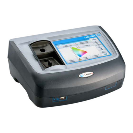
Installation Front and back view Figure 1 Front view USB port type A Touch screen Cuvette compartment cover On/off switch... -
Page 15: Power Connections
Installation Figure 2 Back view Ethernet port USB port type A USB port type B Connection for benchtop power supply Power connections WA R N I N G Electrical and fire hazards. Only use the supplied benchtop power supply LZV844. 1. -
Page 16: Interfaces
Installation Interfaces The instrument has three USB ports and one Ethernet port as standard. They are located on the front and rear of the instrument (Figure 1, page Figure 2, page 15). The USB type A ports are used for communications with a printer, USB memory stick or keyboard. -
Page 17: Installation Of Cuvette Adapter Z
Installation Cell compartment (2) for: The following cell types can be used in cell compartment (2). • Without cuvette adapter Z in the cuvette compartment (2), you can insert 50 mm cuvettes. • With cuvette adapter Z: 10 mm square cuvettes. Note: These cuvettes must be inserted with cuvette adapter Z. - Page 18 Installation Figure 3 Cuvette compartments and cuvette adapter Z Cuvette compartment (1) for round cuvettes Cuvette compartment (2) for square cuvettes, cuvette adapter Z installed...
-
Page 19: Section 4 Start Up
N O T I C E All screen displays in this operating manual correspond to the LICO 690. The screen displays of the LICO 620 may differ. Switch on the instrument, startup process 1. Connect the power cable to the mains outlet. -
Page 20: Sleep Mode
Start Up The Main Menu is displayed when diagnostics are completed. Note: section 5.1.3, page 22 contains a detailed description of the main menu. Sleep mode The instrument can be put into sleep mode. 1. Briefly press the power switch next to the screen. The "Sleep mode"... -
Page 21: Section 5 Standard Programs
Section 5 Standard programs Overview 5.1.1 Tips for using the touch screen The whole screen responds to touch. To choose an option, tap with a fingernail, fingertip, an eraser or a specialised stylus. Do not touch the screen with sharp objects, such as the tip of a ballpoint pen. -
Page 22: Main Menu
Function is used to determine color values such as Hazen, COLOR MEASUREMENT MODE Gardner and Saybolt. The LICO 690 also offers three-dimensional, absolute Color measurement colorimetric values, as well as the color scales of CIE L*a*b*, Hunter Lab or the European Pharmacopoeia. -
Page 23: Instrument Setup
Standard programs Instrument Setup 1. In the main menu, select the menu option Instrument setup. A selection of functions appears in order to configure the functions of the instrument. 5.2.1 Operator ID Use this option to enter up to 30 sets of operator initials (up to ten characters each) into the instrument. -
Page 24: Sample Id
Standard programs 10. With Back the device returns to the menu "Instrument Setup". Press Logout to log out of an active operator ID. Press Login to activate a selected operator ID. Press Options to enter, change or delete additional operator IDs. -
Page 25: Sample Id With Hand-Held Scanner Method 1
Standard programs 6. To number the sample IDs sequentially (e. g. Inflow (01) etc.), press Add Number. • Use the arrow keys to specify the first number of the sequence. • Use the key between the arrow keys to enter the first number of the sequence using the alphanumeric keypad. -
Page 26: Sample Id With Hand-Held Scanner Method 2
Standard programs 3. Read barcode with hand-held scanner. 4. The sample ID can have the current date and time, a sequential number and a colour allocated to it. Select the required options or a colour. 5. Press OK to confirm the entry. 6. -
Page 27: Security Settings
Standard programs All *.TXT and *.CSV files in the Sample ID folder will be displayed for selection. 5. Select the desired file with 6. Transfer the displayed sample ID list with DONE 5.2.3 Security settings The "Security" menu contains a variety of security settings to control access to various functions. -
Page 28: Assign Operator Security Level
Standard programs 5. Select the required function and press Setup. 6. Select the required security level (two keys, one key or off) and confirm using OK. 7. Press OK to return to the "Security" menu. 8. Press On to activate the new settings of the security list. 9. - Page 29 Standard programs 4. Press Operator Password. 5. Enter the operator password and confirm with OK. 6. Press Security Level: <Off>. 7. Enter the security password and confirm with OK. The current security level for the selected operator is shown. 8. Select the required security level for this operator ID and confirm with OK.
-
Page 30: Deactivate Password
Standard programs The operator ID is displayed with the selected security level. 10. Activate the selected operator ID by pressing Login. 11. Enter the operator password. 12. Confirm with OK and return to "Instrument Setup". 5.2.3.2 Deactivate password 1. Press Security in the "Instrument Setup" menu. 2. - Page 31 Standard programs 2. Press Date Format for the date. 3. Press OK to confirm the entry. 4. Press Time Format for the time. 5. Press OK to confirm the entry. 6. Press OK to confirm the entry. 7. Enter the current date and time. Change the information using the arrow keys.
-
Page 32: Sound Settings
Standard programs 5.2.5 Sound settings 1. Press Sound Settings in "Instrument Setup". The following options will be displayed: • All: Activates/deactivates a sound with a variable volume for every function, with the exception of the timer. • Touch screen: Activates/deactivates a short sound with variable volume every time the screen is touched. -
Page 33: Printer Setup
Standard programs 1. Press PC & Printer in "Instrument Setup". A list with information about the connections opens. 5.2.6.1 Printer setup 2. Press Printer. 3. Press Setup to display the Printer Setup screen. Printer Setup: • Resolution: Font size • Paper: Paper size •... -
Page 34: Print Data
Standard programs 6. Press Paper to select the paper size. Select between: • Letter, • Monarch, • Executive, • 7. Press OK to confirm the entry. Note: Press OK again to return to the "Instrument Setup" menu. 5.2.6.2 Print data 1. -
Page 35: Network Setup
Standard programs 5.2.6.4 Network setup N O T I C E Network and access point security is the responsibility of the customer that uses the wireless instrument. The manufacturer will not be liable for any damages, inclusive however not limited to indirect, special, consequential or incidental damages, that have been caused by a gap in, or breach of network security. - Page 36 Standard programs 6. Press IP address and enter the address. In conjunction with the IP address of an instrument, the subnet mask establishes which IP addresses are located within the local network. 7. Press Subnet Mask and enter the address. A Gateway enables data communication in networks that are based on varying protocols.
- Page 37 Standard programs 11. Press Netdrive and run a netdrive setup. As an example, Netdrive Setup is described here. The target site can be defined by IP address or a server name. 12. Press IP-Address and enter the IP address or select Server Name and enter a server name.
-
Page 38: Power Management
Standard programs 19. Press Factory Default to restore the network configuration to the factory defaults. 5.2.7 Power Management 1. Press Power Management in "Instrument setup". 2. Press Sleep Timer and then OK. 3. Select the required time span after which the instrument will go into energy-saving sleep mode if it is not used (refer to 20), and confirm with OK. -
Page 39: Color Values
Standard programs In addition, the LICO 690 can store 100 reference color measurements, 1000 single and multi-wavelength measurements, 20 wavelength scans and 20 time scans. A complete record of the analysis is stored, including the Date, Time, Results, Sample ID and Operator ID. - Page 40 Standard programs 2. Press Color Log. A listing of the stored data is displayed. 3. Press Filter: On/Off. The function Filter Settings is used to search for specific items. 4. Activate On. The data can now be filtered using the following selection criteria.
-
Page 41: Send Color Values From The Measured Data Memory
Standard programs 7. Press Options and Graph Data. A graphic trend of all color values stored in the selected period and color system is displayed. The trend shows a visual impression of the measured process values, e.g. during production supervision in the shift operation. 8. -
Page 42: Delete Color Values From The Measured Data Memory
Standard programs 1. Plug the USB memory stick into the USB-A port on the instrument or connect the instrument to a network drive (see section 5.2.6.4, page 35). 2. In the main menu, press the Recall Data option. 3. Select the data category to be transferred, e. g. Color Log. A list of the selected measurement data is displayed. -
Page 43: Control Charts For Data From The Aqa Log
Standard programs 5.3.2 Control charts for data from the AQA Log 1. In the main menu, press the Recall Data menu option. 2. Press AQA Log. A listing of the stored data is displayed. 3. Press Filter: On/Off. 4. Activate On. 5. -
Page 44: Data Log (Only Lico 690)
Standard programs The measured standard concentrations are displayed graphically with the control limits and date. 5.3.3 Data log (only LICO 690) Measurement results from the photometric measurements of single and multi-wavelengths can be found under Recall Data Data Log. 5.3.3.1 Automatic/manual saving of single and multi-wavelength measurements... -
Page 45: Recall Single And Multi-Wavelength Measurements From The Measured Data Memory
Standard programs 5.3.3.2 Recall single and multi-wavelength measurements from the measured data memory 1. In the main menu, press the Recall Data menu option. 2. Press Data Log. A listing of the stored data is displayed. 3. Press Filter: On/Off. The function Filter Settings is used to search for specific items. -
Page 46: Send Single And Multi-Wavelengths From The Measured Data Memory
Standard programs 6. Press View Details to get more information. 7. Press Options and View Graph. A graphic trend of all wavelength measurements stored in the selected period is displayed. The trend shows a visual impression of the measured process values, e.g. during production supervision in the shift operation. - Page 47 Standard programs file, to a directory with the name DataLog on a USB mass storage device or a network drive. The file can then be processed using a spreadsheet program. The file name has th format: DL_Instrument Type_Serial Number_Year-Month-Day_Hour_ Minute_Second.csv or DL_Instrument Type_Serial Number_Year-Month-Day_Hour_ Minute_Second.xml.
-
Page 48: Delete Single And Multi-Wavelengths From The Measured Data Memory
Note: The number in parentheses is the total number of data sets assigned to this selection. 5.3.4 Wavelength scan and time course (LICO 690 only) You can save 20 data records for the wavelength scan and 20 data records for the time course. The data must be stored manually after it is displayed. -
Page 49: Recall Stored Data From Wavelength Scan Or Time Course
1. In the main menu, press the Recall Data menu option and then Wavelength Scan or Time Course. 2. Press Options and then the PC & Printer icon to send the data to a USB memory stick, to a printer or to a PC with Hach Data Trans. •... - Page 50 Standard programs • If a USB memory stick is connected, the files will be automatically sent to the USB memory stick as xml or csv files in the file folder "WLData (data of a wavelength scan) or "TCData" (data of a time course). The file name has the following format: •...
-
Page 51: Delete Stored Data From Wavelength Scan Or Time Course
Standard programs 5.3.4.4 Delete stored data from wavelength scan or time course 1. In the main menu, press the Recall Datamenu option and thenWavelength Scanor Time Course. A listing of the stored data is displayed. 2. Highlight any data to delete. 3. - Page 52 Standard programs 4. Define the trend settings according to sample ID, operator ID, time interval and parameter. 5. Use control limits to define the upper and lower limits that are displayed in the graphic. 6. Select the required trend and confirm with Select. 7.
-
Page 53: Take And Prepare Samples
Standard programs 8. Press Information to recall an overview of the parameter information. 9. Press Add Data to include additional measured values in the trend. Take and prepare samples Take a representative sample from the product you wish to measure in accordance with DIN EN ISO 15528 (or ASTM D3925-02). -
Page 54: Color Measurement
Standard programs any temperature between ambient temperature and 150 °C (302 °F). N O T I C E The samples must be clear and free of turbidity. If products in paste or solid form cannot be measured directly, the product must be melted before being transferred to the cuvettes/sample cells. -
Page 55: Take A Color Measurement
Standard programs To use the 10 mm square cuvette and 11 mm round cuvettes, adapter Z must be inserted into the cuvette compartment (2). For measurements with 50 mm square cuvettes, you must remove the adapter. 5.5.1 Take a color measurement 1. -
Page 56: Touch-Sensitive Areas In Measurement Mode
Standard programs 5. Insert the test cuvette. The measurement starts automatically. The result of the color calculation is displayed. Note: The bar on the right next to the result shows the result relative to the measurement range. 6. For the next measurement, remove the cuvette and insert the next sample cuvette, or press Measure to measure the same sample again. -
Page 57: Parameter Setup Options
Standard programs 5.5.1.2 Parameter setup options Press Options to set up the parameter. Table 4 Color measurement options Options Description More For further Options Symbol: Store Data, if Instrument Setup > Data Log Setup > Auto Store: Off is selected. Save icon Symbol: Recall Data, if Instrument Setup >... -
Page 58: Change The Color Scale After A Measurement
Standard programs 5.5.1.3 Change the color scale after a measurement 1. Press the touch-sensitive area, e. g. Color Value Gardner. 2. A list of all color scales is displayed. 3. Select the required scale. 4. Press OK to confirm. The current result of the actual reading and all further measurements will be displayed in the selected color scale. -
Page 59: Determination Of The Hazen Color Value (Pt-Co Or Apha Method)
Standard programs scale determines the depth of color of clear liquids like solvents, plasticisers, resins, oils and fatty acids, whose color is similar to that of a solution of iodine and potassium iodide of the same thickness. For iodine color values of less than or approximately 1, the determination of the Hazen value according to DIN-ISO 6271 is to be preferred. -
Page 60: Determination Of The Saybolt Color Number (Astm D 156)
11 mm or 50 mm. A longer path length increases the measurement accuracy (50 mm recomended). 5.5.8 Color determinations only by LICO 690 5.5.8.1 Color determination according to the European Pharmacopoeia (EP) The method used to determine coloration according to the Europeean Pharmacopoeia (Pharm.Eur.) corresponds to the... - Page 61 Standard programs Table 5 Specified scale Character Description <> between The color number of the sample is between those of two reference solutions The color numner of the sample does not match any reference solution in this scale, but the ->...
- Page 62 Standard programs The Lab* value shows the color difference of the measured sample relative to the stated reference solution B4. The E* value shows the three-dimensional color difference of the measured sample relative to the stated reference solution B4. 5. Press Return to change the option for the color matching function.
- Page 63 Standard programs Graph for the brownish yellow scale BY. Graph for the yellow scale Y. Graph for the red scale R. If the CIE L*a*b* value of the sample does not correspond to any reference solution in a selected scale, the > (next) symbol appears, followed by the next reference solution with the smallest color difference E*.
-
Page 64: Color Determination According To The Us Pharmacopoeia (Usp)
Standard programs If the color space of the sample is outside the graph of a color comparison scale, the error message Value outside! appears above the graph. 5.5.8.2 Color determination according to the US Pharmacopoeia (USP) The method used to determine color according to the US Pharmacopoeia corresponds to the specifications in Chapter 631 "Color and Achromicity"... -
Page 65: Color Determination According To The Chinese Pharmacopoeia (Chp)
Standard programs The touch-sensitive area around the color standard is active. 4. Press the area around the color standard (in this case B). The color axis a*, b* and the loci of the sample (+) is displayed as well as the USP color standards. The color matching result is displayed graphically. -
Page 66: Determination Of The Hess-Ives Color Number
Standard programs 5.5.8.7 Determination of the Hess-Ives color number The Hess-Ives color number is used in the cosmetics industry to evaluate the color of fat derivatives. It combines in one number the weighted color intensities, which represent the red, green and blue parts of the transmittance spectrum of the sample at 3 wavelengths. -
Page 67: Determination Of The Acid Wash Color
Standard programs 5.5.8.9 Determination of the Acid wash color ASTM D848 - 09 is the standard test method for the acid wash color in the "aromatic hydrocarbon" industry. The test procedure covers the determination of the acid wash color for benzene, toluene, xylene, refined solvents such as naphtha and similar aromatic hydrocarbons. -
Page 68: Measurement Of Color Differences (Lico 690 Only)
Standard programs 5.6 Measurement of color differences (LICO 690 only) The mode for color difference measurement is used to determine a quantitative color difference between a reference (R) and a sample (P) in the three-dimensional color space (CIE L*a*b* or Hunter Lab). - Page 69 Standard programs 7. Press Option for Parameter Setup. Table 6 contains additional information on the program options. Table 6 Options for color difference measurement Options Description More For further Options Symbol: Store Data, if Instrument Setup > Data Log Setup > Auto Store: Off is selected. Save icon Symbol: Recall Data, if Instrument Setup >...
-
Page 70: View Graph/Table/Values
Standard programs 5.6.1.1 View graph/table/values 1. Press Options > View Graph to display the transmittance graph for the sample (black line) and the reference (red line) in the wavelength range of 380 nm to 720 nm on the x-axis and the % transmittance on the y-axis. In the middle of the graph a dotted cursor line is displayed. -
Page 71: Take A Color Difference Measurement With Stored Reference Values
Standard programs 5.6.2 Take a color difference measurement with stored reference values 1. Press Color Difference Measurement from the Main Menu. 2. Press Select Reference. 3. A list of available references is displayed. 4. Press the required reference. 5. Press Select Reference to confirm. 6. -
Page 72: Photometry (Lico 690 Only)
Standard programs 5.7 Photometry (LICO 690 only) In the photometry mode, photometric measurements can be carried out as: • Single wavelength measurements • Multi wavelength measurements • Time course • Wavelength scans 5.7.1 Single Wavelength (absorbance, concentration and transmittance readings) The Single Wavelength mode can be used in three ways. - Page 73 Standard programs Table 7 Options for Single Wavelength(Continued) Options Description To input the wavelength setting. Use the alphanumeric keypad to enter the reading wavelengths. Wavelength The entered wavelength must be in the range from 320-110 nm. Send Data icon To send data to a printer, computer or USB memory stick (Type A) Concentration Factor Multiplication factor for converting absorbance values into concentration values.
-
Page 74: Take Single Wavelength Readings (Single Reading)
Standard programs 5.7.1.2 Take single wavelength readings (single reading) 1. Insert the zero solution cell into the cell compartment. 2. Press Zero. Note: The Read key is only active after the zero reading has been completed. 3. Insert the analysis cell into the cell compartment. 4. - Page 75 Standard programs Table 8 Multi wavelength setup options(Continued) Options Description To input the wavelength setting. Use the alphanumeric keypad to enter the reading wavelengths. Wavelength The entered wavelength must be in the range from 320–1100 nm. Send Data icon To send data to a printer, computer or USB memory stick (Type A) Concentration Factor Multiplication factor for converting absorbance values into concentration values.
- Page 76 Standard programs refers to the coefficient at wavelength 1 refers to the coefficient at wavelength 2, etc. If a subtraction has to be completed, the factors can be entered with a minus sign. 6. To change the wavelength, press the x key. 7.
-
Page 77: Complete A Reading In The Multi Wavelength Mode
Standard programs 5.7.2.2 Complete a reading in the Multi Wavelength mode 1. Insert the zero solution cell into the cell compartment. 2. Press Zero. Note: The Read key does not become active until the zero reading has been completed. 3. Insert the analysis cell into the cell compartment. 4. - Page 78 Standard programs Table 9 Time course options(Continued) Options Description Send Data To send Data to a printer, computer or USB memory stick (Type A) Recall measurement Recall saved measurement data, wave-length scans or time courses, see section 5.3, page data Instrument Setup Basic data of the instrument, refer to section 5.2, page...
-
Page 79: Time Course Scan Reading
Standard programs 5.7.3.2 Time course scan reading After all scan parameters have been selected, the instrument must then be zeroed. Afterward the sample can be analyzed. 1. Insert the zero solution cuvette into the cuvette compartment and close the cuvette compartment cover. 2. -
Page 80: Wavelength Scan Mode - Recording Of Absorbance And Transmission Spectrums
Standard programs Table 10 Navigating the time scan Cursor function/ Description Zoom function Delta mode: A second cursor is highlighted. The position of the fixed cursor was previously defined in Cursor mode Single. Use the active cursor to select any point on the reading curve. The difference to the fixed cursor is shown on the curve. -
Page 81: Set Up The Wavelength Scan
Standard programs 5.7.4.1 Set up the wavelength scan In the main menu, press the Wavelength Scan menu option. Press Options for Parameter Setup. Table 11 Options during wavelength scan Option Description More For further Options Symbol: Store Data, if Instrument Setup > Data Log Setup > Auto Store: Off is selected. Save icon Symbol: Recall Data, if Instrument Setup >... - Page 82 Standard programs Set the wavelength range 1. Press the key in the "Options" menu to select the wavelength range and the wavelength step. 2. Press the upper left key to select the lower wavelength. 3. Enter the lower wavelength. 4. Press OK to confirm. 5.
-
Page 83: Perform A Wavelength Scan
Standard programs Integral The Integral applies to the whole wavelength range of the scan. 1. Press Integral: Off in the "Options" menu. 2. Highlight On to show the Integral. 3. To find the integral of other wavelength ranges, change the wavelength range and scan again. -
Page 84: Work With Reference Scans
Standard programs 3. Press Zero. During the scan of the base line, "Zero calibration" is shown in the screen. 4. Insert the prepared analysis cuvette into the cuvette compartment and close the cuvette compartment cover. 5. Press Read. Under the graph, the display "Reading..." appears, and a graph of the absorbance or transmittance values for the scanned wavelengths is continuously displayed. - Page 85 Standard programs 2. The reference curve is displayed in orange. The absorbance or transmittance value and the associated wavelength are highlighted in grey. Note: A black and an orange field are displayed in the top left of the screen. The orange box relates to the reference scan and the black one relates to the current wavelength scan.
- Page 86 Standard programs 4. The reference graph is displayed in orange. The absorbance or transmittance value and the associated wavelength are displayed in orange. • In addition, the difference of the absorbance and/or transmittance value between the two scans (measured scan and reference scan) is indicated/highlighted at each position of the cursor.
-
Page 87: Section 6 Advanced Operations
1. Press Instrument Information in the "System Check" menu. 2. The model, serial number and software version are displayed. 6.1.2 Update the instrument software 6.1.2.1 Software update with USB memory To obtain the software for the update from the Internet at www.hach.com:... -
Page 88: Software Update With Network Connection
Advanced Operations 1. Go to http://www.hach.com. 2. Select the country. 3. Enter LICO into the "Search" field. 4. Select Documents and Software from the field "according to". 5. Navigate to the corresponding file for download. 6. Save the file to a USB storage device or PC. - Page 89 Advanced Operations 3. Press Edit. An automatic menu guidance queries values (filters, wavelength, nominal values and tolerances) given in the quality control certificate, to the following specifications: • Stray light • Photometrical accuracy • Wavelength accuracy 4. Press OK when all values are entered and the overview is displayed.
-
Page 90: Aqa Analytical Quality Assurance
Advanced Operations After the last reading the results are displayed. 12. Press PC & Printer icon to send the data to a USB memory stick, PC or to a printer. The files will be stored automatically as CSV files (Comma Separated Value). -
Page 91: Perform Aqa Standard Measurement
Advanced Operations 4. Enter the concentration, unit, confidence range and unit by pressing the relevant fields. 5. Press OK to confirm the entry. 6. All the standard solutions entered are shown on the screen. 7. Select Options for further editing. Select New to define a new standard. -
Page 92: Instrument Backup
Advanced Operations 6.1.5 Instrument backup Prior to the next service date, the "Instrument Backup" offers the opportunity to store all programs, measurement data, user IDs, passwords, as well as all adjustable data on a USB stick. 1. Press Instrument Backup in the "System Check" menu. 2. -
Page 93: Service Menu
Advanced Operations 6.1.6 Service menu Use of the service menu requires a service code. This menu is reserved exclusively for the service staff of the manufacturer for service work. 6.1.7 Service time In order to make sure a regular inspection is performed, an automatic memory reference for the service times can be entered. -
Page 94: Toolbar
Advanced Operations After a lamp is replaced, the display of the switch-on cycles is reset to 0. 1. Press Lamp History in the "System Check" menu. 2. Press Reset and the lamp data are reset. 3. Press OK to return to the "System Check" menu. Toolbar There is a toolbar with various programs on the right-hand side of the screen. -
Page 95: Timer
Advanced Operations 6.2.3 Timer Use this function to activate a timer at any time. 1. In the toolbar, press Timer. 2. Enter the required time and confirm with OK. The count-down starts automatically. 3. Press Close to let the timer run in the background. Press Cancel to stop the timer. - Page 96 Advanced Operations...
-
Page 97: Section 7 Maintenance
Section 7 Maintenance C A U T I O N Potential Chemical, Biological Eye and Skin Hazards. Only qualified personnel should conduct the tasks described in this section of the manual. N O T I C E Remove all cells remaining in the instrument. Dispose of the cells or their contents in an authorized manner. -
Page 98: Cuvettes/Cells
Maintenance 7.1.3 Cuvettes/cells C A U T I O N Potential Chemical/ Biological Exposure Hazards. User correct laboratory practices if a risk of chemical exposure exists. 1. After use, clean the glass cells with cleaning agents. 2. Afterwards, rinse the cuvettes/sample cells several times with tap water and then thoroughly with deionized water. - Page 99 Maintenance 6. Using a cross-head screwdriver, remove the two screws from the lamp holder. 7. Lift out the lamp holder upwards. 8. Turn the lamp holder so that the connector with the cable guide points forwards. 9. Push the clamp slide as far as possible to the right (Step 1). 10.
-
Page 100: Cell Compartment (2) Replacement
Maintenance To fit a new lamp carry out the procedure in reverse. N O T I C E Only hold lamp at lamp holder. Avoid touching the glass, as substances on the skin can bake onto the lamp bulb and thus accelerate the ageing process of the lamp. - Page 101 Maintenance 1. Switch off instrument. 2. Remove the power cable from the instrument. 3. Open the cuvette compartment cover and remove cuvette adapter Z. 4. Using a cross-head screwdriver, loosen the two screws on the bottom of the cuvette compartment. 5.
- Page 102 Maintenance...
-
Page 103: Section 8 Troubleshooting
Section 8 Troubleshooting Error displayed Definition Resolution An error occurred when uploading Restart the process or contact the the instrument data. manufacturer or national agent. An error occurred when reading from Restart the process or contact the the USB memory stick. manufacturer or national agent. - Page 104 Troubleshooting Error displayed Definition Resolution Fault Remove the cuvette/sample cell from Test program stopped! Test program stops when the instrument the cell compartment. Please remove the cuvette is started Press OK. Close the lid. Error Selfcheck stopped. Contact the manufacturer or national Electronic defect Hardware error.
- Page 105 Troubleshooting Error displayed Definition Resolution Save the update file again and repeat Update file is faulty. Error during update. the procedure. USB memory stick is not connected. Update not possible. Check the USB memory stick. Web server cannot be reached. Instruments homepage not available Try the connection again later.
- Page 106 Troubleshooting...
-
Page 107: Section 9 Replacement Parts
50 mm square cuvettes with cap, PMMA, 20 units LZM381 50 mm square cuvettes, PMMA, 50 units LZM130 USB flash drive LZV791 Hach Lange Online Data for direct data transfer to MS Excel LZV799 Protective cap for USB port LZV881 USB extension cord LZV567 Ethernet cable, shielded, 2 m in length. - Page 108 Replacement Parts...
-
Page 109: Section 10 Limited Warranty
In the event that a defect is discovered during the warranty period, Hach Company agrees that, at its option, it will repair or replace the defective product or refund the purchase price excluding original shipping and handling charges. Any product repaired or replaced under this warranty will be warranted only for the remainder of the original product warranty period. - Page 110 Limited warranty incidental or consequential damages of any kind for breach of warranty or negligence.
-
Page 111: Index
Index Absorbance Formula ..........75 Ethernet communication .......... 35 Acid wash color ............67 Ethernet port ............16 ADMI color number ..........66 European Pharmacopoeia ........60 Alphanumeric keypad ..........21 APHA method ............59 ASTM D 1500 ............59 Factory Service ............ - Page 112 Index Specifications ............. 7 Spectral bandwidth ............. 7 Operator ID .............. 23 Startup melody ............19 Optical Checks ..........88, 90, 93 Startup process ............19 Output Checks ............93 Stored Data .............. 39 Overview of Product/Function ........10 Stored programs ............72 Stray light ..............
- Page 114 SWITZERLAND Fax (970) 669-2932 Fax +49 (0) 2 11 52 88-210 Tel. +41 22 594 6400 orders@hach.com info-de@hach.com Fax +41 22 594 6499 www.hach.com www.de.hach.com © Hach Company/Hach Lange GmbH, 2012, 2018, 2021, 2023 All rights reserved. 05/2023, Edition 8...
Need help?
Do you have a question about the LICO 690 and is the answer not in the manual?
Questions and answers