Table of Contents
Advertisement
Quick Links
DESCRIPTION
Demonstration Kit DC3080-KIT features
ADJ, wireless Li-Ion Charger with 1.2V Step-Down DC/
DC Converter. This kit comprises a wireless transmitter
DC3081A, a wireless receiver DC3078A and two 6mm
application-sized receivers DC3079A.
DC3078A wireless charger receiver incorporates an exter-
nal trickle charge circuit that reduces the charge current to
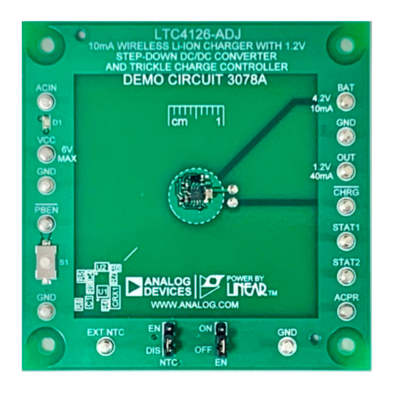
BOARD PHOTO
1 x DC3078A (LTC4126-ADJ) Receiver Demo Board
2 x DC3079A (LTC4126-ADJ) 6mm Application-Sized Receiver Demo Board
1 x DC3081A (LTC6990) Transmitter Demo Board
PERFORMANCE SUMMARY
SYMBOL
PARAMETER
V
DC3081A Voltage Input
IN
I
DC3078A Charge Current in CC Mode
BAT
V
DC3078A Float Voltage
BAT
f
DC3081A Drive Frequency
DRIVE
f
DC3081A Resonant Tank Frequency
TX_TANK
f
DC3078A Resonant Tank Frequency
RX_TANK
AIR-GAP
Airgap Between DC3078A and DC3081A
TYPICAL APPLICATION SCHEMATIC
DC3078A
V
IN
4.5V TO 5.5V
200mA
OE
SET
243k
DIV
LTC
®
Specifications are at T
CONDITIONS
I
BAT
AIR-GAP
4mm TO 8mm
4.7µF
V+
LTX
6.8µF
C
TX
57nF
LTC6990
M1
OUT
GND
Figure 1. 10mA Wireless Charging System Using DC3078A and DC3081A
DEMO MANUAL DC3080A-KIT
10mA Wireless Charger
4126-
1mA when a deeply discharged battery with voltage lower
than 2.8V is plugged in. The combination of DC3081A
transmitter and DC3078A receiver can charge a single
Li-Ion battery at up to10mA with an airgap of 4.0mm to
8.0mm.
Design files for this circuit board are
All registered trademarks and trademarks are the property of their respective owners.
= 25°C
A
= 10mA
ACIN
LTC4126-ADJ
L
RX
13µF
C
RX
47nF
STAT1
DIGITAL
STAT2
I/O
ACPR
PBEN
GND
EN
PUSHBUTTON
LTC4126-ADJ
Demonstration Kit
MIN
TYP
4.5
10
4.2
205
255
203
4
DC3081A
10mA
BAT
NTC
Li-Ion
R
+
NTC
Battery
R
BIAS
100k
V
CC
LED
1k
CHRG
2.2µF
PROG
V
CC
DIS
OUT
1.2V
V
IN
OUT
30.1k
GND
40mA
6.34k
ADM8642T100
1µF
TRICKLE CHARGE WHEN
8.87k
V
IS BELOW 2.8V
BAT
available.
MAX
UNITS
5.5
V
mA
V
kHz
kHz
kHz
8
mm
Rev. 0
1
Advertisement
Table of Contents

Related Manuals for Linear ADI Power DC3080A-KIT


Summary of Contents for Linear ADI Power DC3080A-KIT
- Page 1 DEMO MANUAL DC3080A-KIT LTC4126-ADJ 10mA Wireless Charger Demonstration Kit DESCRIPTION Demonstration Kit DC3080-KIT features 4126- 1mA when a deeply discharged battery with voltage lower ® ADJ, wireless Li-Ion Charger with 1.2V Step-Down DC/ than 2.8V is plugged in. The combination of DC3081A DC Converter.
-
Page 2: Board Photo
DEMO MANUAL DC3080A-KIT BOARD PHOTO Figure 2. DC3078A Front Figure 3. DC3078A Back Figure 4. DC3079A Front Figure 5. DC3079A Back Figure 7. DC3081A Back Figure 6. DC3081A Front Rev. 0... -
Page 3: Quick Start Procedure
DEMO MANUAL DC3080A-KIT QUICK START PROCEDURE Refer to Figure 9 and Figure 11 for the proper measure- 6. When OUT is on, set LD1 to CC mode. Slowly tune up ment equipment setup and follow the procedure below: the load current to 40mA. VM2 should be regulated at around 1.2V 1. - Page 4 DEMO MANUAL DC3080A-KIT TEST SETUP BATTERY EMULATOR RBAT1 50Ω 2.5V-4.2V 0-40mA Figure 9. Test Setup for DC3078A Receiver 4.5V-5.5V Figure 10. Test Setup for DC3081 Transmitter Rev. 0...
-
Page 5: Test Setup
DEMO MANUAL DC3080A-KIT TEST SETUP Figure 11. Test Setup for DC3079A 6mm Application-Sized Receiver Figure 12. DC3078A and DC3081A Combination Rev. 0... -
Page 6: Theory Of Operation
DEMO MANUAL DC3080A-KIT THEORY OF OPERATION The DC3080A-KIT demonstrates the operation of When BAT pin is lower than 2.8V before charging, the LTC4126-ADJ, wireless battery charger. This kit is com- comparator on board will inject current to the PROG pin posed of a DC3081A transmitter board, a DC3078A resistor once V is available. -
Page 7: Parts List
DEMO MANUAL DC3080A-KIT PARTS LIST ITEM REFERENCE PART DESCRIPTION MANUFACTURER/PART NUMBER DC3078A Evaluation Receiver: Required Circuit Components CAP ., 2.2uF , X5R, 16V, 20%, 0402 TDK, C1005X5R1C225M050BC CAP ., 1uF , X5R, 16V, 10%, 0402 AVX, 0402YD105KAT2A CAP CER 2.2UF 6.3V X5R 0201 MURATA, GRM033R60J225ME47D CRx1 CAP ., 0.047uF , C0G, 25V, 5%, 0805, AEC-Q200... - Page 8 DEMO MANUAL DC3080A-KIT ITEM REFERENCE PART DESCRIPTION MANUFACTURER/PART NUMBER DC3081A Transmitter: Required Circuit Components CAP ., 4.7uF , X5R, 10V, 10%, 0402 TDK, C1005X5R1A475K050BC CAP ., 0.1uF , X5R, 10V, 10%, 0402 AVX, 0402ZD104KAT2A CTx1 CAP ., 0.047uF , C0G, 50V, 5%, 1206 MURATA, GCM31M5C1H473JA16L CTx2 CAP ., 0.01uF , C0G, 25V, 5%, 0603...
-
Page 9: Schematic Diagram
DEMO MANUAL DC3080A-KIT SCHEMATIC DIAGRAM Rev. 0... - Page 10 DEMO MANUAL DC3080A-KIT SCHEMATIC DIAGRAM Rev. 0...
- Page 11 DEMO MANUAL DC3080A-KIT SCHEMATIC DIAGRAM Rev. 0 Information furnished by Analog Devices is believed to be accurate and reliable. However, no responsibility is assumed by Analog Devices for its use, nor for any infringements of patents or other rights of third parties that may result from its use. Specifications subject to change without notice.
- Page 12 DEMO MANUAL DC3080A-KIT ESD Caution ESD (electrostatic discharge) sensitive device. Charged devices and circuit boards can discharge without detection. Although this product features patented or proprietary protection circuitry, damage may occur on devices subjected to high energy ESD. Therefore, proper ESD precautions should be taken to avoid performance degradation or loss of functionality. Legal Terms and Conditions By using the evaluation board discussed herein (together with any tools, components documentation or support materials, the “Evaluation Board”), you are agreeing to be bound by the terms and conditions set forth below (“Agreement”) unless you have purchased the Evaluation Board, in which case the Analog Devices Standard Terms and Conditions of Sale shall govern.
Need help?
Do you have a question about the ADI Power DC3080A-KIT and is the answer not in the manual?
Questions and answers