Advertisement
Quick Links
QUICK START GUIDE FOR DEMONSTRATION CIRCUIT 1339
DESCRIPTION
Demonstration
circuit
LTC2302 low noise, 500ksps, 12-Bit, ADC.
The LTC2302 has an SPI compatible serial
interface that can be used to select channel
polarity and unipolar or bipolar settings.
DC1339A demonstrates the DC and AC
performance of the LTC2302 in conjunction
with the DC590B QuikEval and DC890B Fast
DAACS data collection boards. Use DC590B
to demonstrate DC performance such as
peak-to-peak noise and DC linearity. Use
1339
features
the
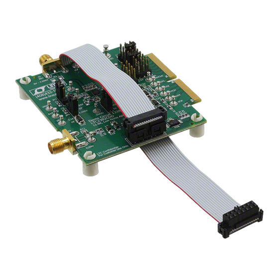
Figure 1. DC1339A Connection Diagram
LOW NOISE, 500KSPS, 12-BIT ADC
DC890B if precise sampling rates are required
or to demonstrate AC performance such as
SNR, THD, SINAD and SFDR. Alternatively,
by connecting the DC1339A into a customer
application, the performance of the LTC2302
can be evaluated directly in that circuit.
Design files for this circuit board are
available. Call the LTC factory.
LTC is a trademark of Linear Technology Corporation
LTC2302
1
Advertisement

Related Manuals for Linear DC1339


Summary of Contents for Linear DC1339
- Page 1 Design files for this circuit board are DAACS data collection boards. Use DC590B available. Call the LTC factory. to demonstrate DC performance such as LTC is a trademark of Linear Technology Corporation peak-to-peak noise and DC linearity. Use Figure 1. DC1339A Connection Diagram...
- Page 2 USB A/B cable. Apply 6V-9V DC to (Pscope.exe version K51 or later) supplied with the 6V-9V and GND terminals. Apply a low DC890B or download it from www.linear.com. jitter signal source to IN+ on connector J1. Complete software documentation is available...
-
Page 3: Hardware Setup
USB A/B cable. Run the (unipolar or bipolar) by right clicking over the evaluation software supplied with DC590 or range indicator in the display. See Figure 5. download it from www.linear.com. The correct control panel will be loaded automatically. HARDWARE SET UP SIGNAL CONNECTIONS JUMPERS J1 SMA connector for IN+. - Page 4 QUICK START GUIDE FOR DEMONSTRATION CIRCUIT 1339 LOW NOISE, 500KSPS, 12-BIT ADC Figure 4. DC1339A Pscope Screenshot...
- Page 5 QUICK START GUIDE FOR DEMONSTRATION CIRCUIT 1339 LOW NOISE, 500KSPS, 12-BIT ADC Figure 5. DC1339A QuikEval Screen Shot...
- Page 6 QUICK START GUIDE FOR DEMONSTRATION CIRCUIT 1339 LOW NOISE, 500KSPS, 12-BIT ADC OVDD OVDD 10uF 6.3V SDO_AT_BUF 0.1uF 0.1uF 2.5V LTC2302CDD NC7SVU04P5X SN74AHCT1G04DCKT 0.1uF 0.1uF CONVST 0V - 4.096V SDO_AT_590 49.9 3.01K (Opt) EXPOSED 47pF 47pF 0.1uF VREF VREF/2 10uF 4.99K 6.3V 4.99K...
- Page 7 QUICK START GUIDE FOR DEMONSTRATION CIRCUIT 1339 LOW NOISE, 500KSPS, 12-BIT ADC 2.5V 2.5V CONV 0.1uF 0.1uF NC7SVU04P5X NC7SZ04P5X_NL CONV 0.1uF 49.9 SDO_AT_BUF 0.1uF 0.1uF NC7SZ66P5X CNVCLK NL17SZ74USG CLK_IN 0.1uF LT1719CS6 1.25V MISO MISO MOSI MOSI 0.1uF SHDN LATCH LATCH 0.1uF LT1719CS6 CNVST...
Need help?
Do you have a question about the DC1339 and is the answer not in the manual?
Questions and answers