Table of Contents
Advertisement
Quick Links
DESCRIPTION
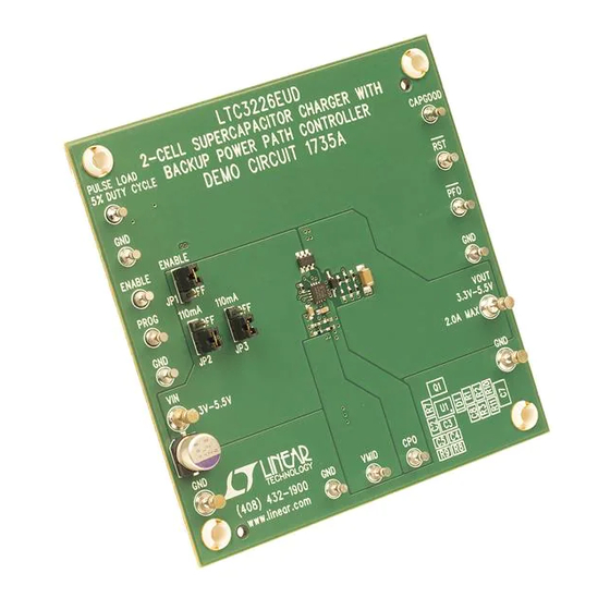
Demonstration circuit DC1735A is a 2-cell supercap
charger with a backup PowerPath™ controller, featuring
the LTC
®
3226. It includes a charge-pump supercapacitor
charger with programmable output voltage, a low drop-
out regulator and a power-fail comparator for switching
between normal and backup modes. The constant-input
current supercapacitor charger is designed to charge two
supercapacitors in series to a resistor programmable out-
put voltage from a 2.5V to 5.3V input supply. The charger
input current limit is programmable by an external resistor
up to 315mA. The internal backup LDO is powered from
PERFORMANCE SUMMARY
SYMBOL
PARAMETER
V
Input Voltage Range
IN
I
Input Current Limit
VIN(ILIM)
V
Supercap Stack Output Voltage
STACK
V
Supercap Midpoint Voltage
MID
The LTC3226 is a 2-cell series supercapacitor charger
designed to back up a Li-ion battery or any system rail in
the range of 2.5V to 5.3V. Its four principle circuit com-
ponents are:
×
×
1. Dual (1
/ 2
) charge pump with an integrated balancer
and a voltage clamp
2. LDO to supply the load current from the charge stored
on the supercapacitors
3. Ideal diode controller to control the gate of the external
MOSFET between V
4. PFI comparator to decide whether to activate the charge
pump to charge the supercapacitor stack or to activate
the LDO to supply the load when V
externally programmed value.
Arrow.com.
Downloaded from
Specifications are at T
CONDITIONS
R
R
and V
IN
OUT
falls below an
IN
DEMO MANUAL DC1735A
2-Cell Supercap Charger With
Backup PowerPath Controller
the supercapacitors and provides up to 2A peak output
current with an adjustable output voltage. When the input
supply falls below the resistor programma-ble power-fail
threshold, the LTC3226 automatically enters a backup state
in which the supercapacitors power the output through
the LDO. The LTC3226 is available in a 16-lead, 3mm
3mm QFN surface mount package with an exposed pad.
Design files for this circuit board are available at
http://www.linear.com/demo
L, LT, LTC, LTM, Linear Technology and the Linear logo are registered trademarks and
PowerPath is a trademark of Linear Technology Corporation. All other trademarks are the
property of their respective owners.
= 25°C
A
= 33.3k
PROG
= 3.83M, R
= 1.21M
CP1
CP2
The LTC3226 has two modes of operation: normal and
backup. If V
IN
threshold voltage, the part is in normal mode and power
flows from V
IN
the internal charge pump chargers the supercapacitor
stack (see Figure 1). If V
part is in backup mode (see Figure 2). In this mode, the
internal charge pump is turned off and the LDO is turned
on to supply the load current from the stored charge on
the supercapacitor stack.
The device includes three open-drain, output status sig-
nals: CAPGOOD, PFO and RST. The CAPGOOD pin is an
open-drain N-channel MOSFET transistor controlled by a
comparator that monitors the voltage on the supercapaci-
LTC3226EUD
MIN
TYP
2.5
315
5.3
2.65
is above an externally programmable PFI
to V
through the external MOSFET while
OUT
is below the PFI threshold, the
IN
×
MAX
UNITS
5.5
V
mA
5.5
V
2.75
V
dc1735Af
1
Advertisement
Table of Contents

Related Manuals for Linear DC1735A


Summary of Contents for Linear DC1735A
- Page 1 L, LT, LTC, LTM, Linear Technology and the Linear logo are registered trademarks and PowerPath is a trademark of Linear Technology Corporation. All other trademarks are the up to 315mA. The internal backup LDO is powered from property of their respective owners.
- Page 2 DEMO MANUAL DC1735A OPERATING PRINCIPLE tor stack. This pin is pulled to ground until the CPO pin comparator which monitors V under all operating modes via the RST_FB pin and reports the status via an voltage rises within 7.5% of the programmed value. Once open-drain NMPS transistor on the RST pin.
- Page 3 75mV and that it recovers within 100μs. that V then falls, tracking CPO until V reaches 2.4V. Verify that RST is low. Figure 3. Proper Measurement Equipment Setup for DC1735A dc1735a F04 Figure 4. Measuring Input or Output Ripple dc1735Af Arrow.com.
- Page 4 DEMO MANUAL DC1735A PARTS LIST ITEM REFERENCE PART DESCRIPTION MANUFACTURER/PART NUMBER Required Circuit Components Cap., Chip, X5R, 4.7μF , 10%, 6.3V, 0603 Murata, GRM188R60J475KE19D Cap., Chip, X5R, 2.2μF , 20%, 10V, 0603 Murata, GRM188R61A225KE34D C4, C5 Cap., Chip, X7R, 0.1μF , 10%, 16V, 0402 Murata, GRM155R71C104KA88D Supercap, 1.2μF , 5.5V, 39mm ×...
- Page 5 Information furnished by Linear Technology Corporation is believed to be accurate and reliable. However, no responsibility is assumed for its use. Linear Technology Corporation makes no representa- tion that the interconnection of its circuits as described herein will not infringe on existing patent rights.
- Page 6 Linear Technology Corporation (LTC) provides the enclosed product(s) under the following AS IS conditions: This demonstration board (DEMO BOARD) kit being sold or provided by Linear Technology is intended for use for ENGINEERING DEVELOPMENT OR EVALUATION PURPOSES ONLY and is not provided by LTC for commercial use. As such, the DEMO BOARD herein may not be complete in terms of required design-, marketing-, and/or manufacturing-related protective considerations, including but not limited to product safety measures typically found in finished commercial goods.
Need help?
Do you have a question about the DC1735A and is the answer not in the manual?
Questions and answers