Advertisement
Quick Links
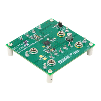
DESCRIPTION
The DC2713A circuit board enables evaluation of the
LTC
4381, low quiescent current surge stopper with
®
9mΩ MOSFET, in 12V to 48V applications. The LTC4381
clamps the output voltage, permitting the load to operate
safely through 100V transients and load dump surges
such as ISO 16750-2 Test A. Current limiting protects the
input supply from output overload and short-circuits. In
the presence of a sustained input overvoltage or output
overload, the LTC4381 shuts off after a delay to protect
the internal power MOSFET.
PERFORMANCE SUMMARY
Surge Stopper (Top Mark)
Typical System Voltage
Output Clamp Select
DC Operating
DC Survival
Load Dump Survival
Current Limit
Maximum Load Current
Cooldown/Retry Delay
Fault Retry Behavior
Arrow.com.
Downloaded from
6µA I
Surge Stopper with 9mΩ MOSFET
Q
Specifications are at T
DC2713A-A
LTC4381-1 (43811)
LTC4381-2 (43812)
12V or 24V/28V
28.5V (JP1 = 28V) or 47V (JP1 = 47V)
8V to 20V (JP1 = 28V) or 38V (JP1 = 47V)
100V
ISO 16750-2 Test A for 12V with 500mA Load
625mA (OUTPUT > 3V), 775mA (OUTPUT < 1V)
500mA
560s (= 9min 20s)
Latch Off
DEMO MANUAL DC2713A
DC2713A is available in four assembly options, from
DC2713A-A to DC2713A-D. DC2713A-A/DC2713A-B
employ a jumper to set the output clamp voltage to
either 28.5V or 47V, to suit 12V or 24V/28V systems.
DC2713A-C/DC2713A-D clamp the output to 66.5V for
48V applications. DC2713A-A/DC2713A-C latch off after
a fault, whereas DC2713A-B/DC2713A-D automatically
restart after a cool down delay.
Design files for this circuit board are
All registered trademarks and trademarks are the property of their respective owners.
= 25°C
A
DC2713A-B
DC2713A-C
LTC4381-3 (43813)
12.5A (OUTPUT > 3V), 15.5A (OUTPUT < 1V)
Auto Retry
Latch Off
LTC4381
available.
DC2713A-D
LTC4381-4 (43814)
48V
66.5V
8V to 60V
60V (Due to D2 TVS)
NA
10A
733ms
Auto Retry
Rev. 0
1
Advertisement

Related Manuals for Linear ADI Power Analog Devices DC2713A


Summary of Contents for Linear ADI Power Analog Devices DC2713A
- Page 1 DEMO MANUAL DC2713A LTC4381 6µA I Surge Stopper with 9mΩ MOSFET DESCRIPTION The DC2713A circuit board enables evaluation of the DC2713A is available in four assembly options, from 4381, low quiescent current surge stopper with DC2713A-A to DC2713A-D. DC2713A-A/DC2713A-B ® 9mΩ...
-
Page 2: Quick Start Procedure
DEMO MANUAL DC2713A QUICK START PROCEDURE DANGER! High voltage testing should be performed the circuit as indicated by the green LED at the out- by qualified personnel only. As a safety precaution, at put. At rated load, the input to output voltage drop least two people should be present during high voltage should be around 50mV for DC2713-A/DC2713A-B and testing. - Page 3 DEMO MANUAL DC2713A QUICK START PROCEDURE INPUT OUTPUT SUPPLY LOAD dc2713A F01 Figure 1. Measurement Equipment Setup Rev. 0 Arrow.com. Arrow.com. Arrow.com. Downloaded from Downloaded from Downloaded from...
-
Page 4: Board Description
DEMO MANUAL DC2713A BOARD DESCRIPTION Overview D1, C1, R1, D2 – V Clamp DC2713A is a 2-layer board with 2oz copper on each The LTC4381 V pin’s absolute maximum voltage is 80V. layer. There are large planes for input, output, and ground. Power is applied from the input to the V pin through Where possible, the input plane is designed to have at... - Page 5 DEMO MANUAL DC2713A BOARD DESCRIPTION INPUT 10V/DIV OUTPUT dc2713A F02 100ms/DIV Figure 2. DC2713A-B Clamps Output to 28.5V During an ISO 16750-2 Test A Input Transient with 500mA Load Rev. 0 Information furnished by Analog Devices is believed to be accurate and reliable. However, no responsibility is assumed by Analog Devices for its use, nor for any infringements of patents or other rights of third parties that may result from its use.
- Page 6 DEMO MANUAL DC2713A ESD Caution ESD (electrostatic discharge) sensitive device. Charged devices and circuit boards can discharge without detection. Although this product features patented or proprietary protection circuitry, damage may occur on devices subjected to high energy ESD. Therefore, proper ESD precautions should be taken to avoid performance degradation or loss of functionality. Legal Terms and Conditions By using the evaluation board discussed herein (together with any tools, components documentation or support materials, the “Evaluation Board”), you are agreeing to be bound by the terms and conditions set forth below (“Agreement”) unless you have purchased the Evaluation Board, in which case the Analog Devices Standard Terms and Conditions of Sale shall govern.
Need help?
Do you have a question about the ADI Power Analog Devices DC2713A and is the answer not in the manual?
Questions and answers