Advertisement
Description
Demonstration circuit 1685A features the
1.6GHz differential ADC buffer driving the LTC2209, a 16-bit
160Msps ADC. The DC1685B is supplied with a bandpass
filter centered at 140MHz between the buffer and ADC.
The filter center frequency can be changed to optimize
performance at different analog input frequencies. Both
single-ended and differential configurations are supported
DC1685A is easy to set up. Refer to Figure 1 for proper
measurement equipment setup and follow the procedure
below:
1. Apply power to the DC1685A 3.3V across the pins
marked V
and PWR_GND and 5V across AMP_POWER
CC
and PWR_GND. The DC1685A requires up to 800mA
from the V
, and 200mA from the AMP_POWER.
CC
2. Supply power to the DC890B fast DAACS board with an
external 6V ±0.5V, 1A on turrets G7(+) and G1(–) or the
adjacent 2.1mm power jack. Unless the DC890B detects
external power, it will not activate the LVDS mode of the
Xilinx Spartan-III FPGA. The FPGA actively terminates
the LVDS repeaters at the outputs of the LTC2209.
3. Connect encode clock to the DC1685A on the SMA
connector marked (J3) Encode Clock. This transformer
coupled input is terminated with a 100Ω at the ADC
clock inputs. For best noise performance the clock input
must be driven with a very low jitter source. When us-
ing a sinusoidal generator, the amplitude should be as
large as possible, up to 13dBm. Using bandpass filters
on the clock and analog inputs will improve the noise
performance by reducing the wideband noise power of
the signals. Data sheet FFT plots are taken with 10 pole
LC filters made by TTE (Los Angeles, CA) to suppress
DEMO MANUAL DC1685A
LTC
6417, a
at the inputs. The DC1685A has been developed from the
®
DC1281A, used to characterize LTC2209 family of ADCs.
Use the DC1685A with a DC890 FastDAACS and PScope™
Software to collect time and frequency data.
Design files for this circuit board are available at
http://www.linear.com/demo/DC1685A
L, LT, LTC, LTM, Linear Technology and the Linear logo are registered trademarks and PScope
is a trademark of Linear Technology Corporation. All other trademarks are the property of their
respective owners.
signal generator harmonics, non-harmonically related
spurs and broadband noise. Low phase noise (jitter)
Agilent 8644B generators are used with the TTE band-
pass filters for the clock and analog input.
4. Connect the analog input to the DC1685A to the SMA
connector marked (J6) IN+ at 140MHz. This input is
capacitively coupled to a 1:4 balun transformer WBC4-11.
5. Start and configure PScope data collection software for
the FastDAACS (DC890) by selecting AutoConfigure.
If the board is not detected, update PScope for latest
software and device list, and then select LTC2209 from
the Configure → Device menu. You can also manually
configure PScope for the LTC2209 by setting the pa-
rameters listed in Table 1.
6. Collect data by clicking on the Collect button. Time and
frequency plots will be displayed in the PScope window.
Consult the DC890B Quick Start Guide for more details.
This procedure contains only one critical sequence.
The user must apply supply voltage before applying
signal power to the analog and clock inputs or forc-
ing a voltage to any other turrets. The user must also
remove the signal to the analog and clock inputs and
voltages on any other turret before turning down the
supply voltage.
LTC6417 and LTC2209
Combo Board
LTC6417
dc1685af
1
Advertisement
Table of Contents

Related Manuals for Linear DC1685A


Summary of Contents for Linear DC1685A
- Page 1 Both http://www.linear.com/demo/DC1685A single-ended and differential configurations are supported L, LT, LTC, LTM, Linear Technology and the Linear logo are registered trademarks and PScope is a trademark of Linear Technology Corporation. All other trademarks are the property of their respective owners.
- Page 2 Bipolar input of the LTC6417 performs a single-ended to differential Positive Edge Clk conversion and provides 6dB voltage gain. For more detail on the LTC6417 and LTC2209, consult Table 2. DC1685A Connector and Jumpers the data sheets. CONNECTOR/ JUMPER FUNCTION Table 3.
-
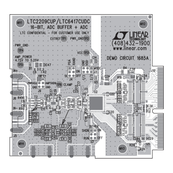
Page 3: Pcb Layout
DEMO MANUAL DC1685A pcB Layout Figure 1. DC1685A Layout dc1685af... -
Page 4: Parts List
DEMO MANUAL DC1685A parts List ITEM REFERENCE PART DESCRIPTION MANUFACTURER/PART NUMBER B1, B4, B5 Ferrite Bead, SMT 1206 MURATA, BLM31PG330SN1L C1, C2, C3 Cap., X7R 0.01µF 100V 10% 0603 AVX, 06031C103KAT2A Cap., NPO 8.2pF 50V 0.25pF 0402 AVX, 04025A8R2CAT2A C5, C7, C8, C11, C12, C15, C16, C20–C23, Cap., X5R 0.1µF 10V 10% 0402... - Page 5 DEMO MANUAL DC1685A parts List ITEM REFERENCE PART DESCRIPTION MANUFACTURER/PART NUMBER I.C., Serial EEPROM TSSOP-8 MICROCHIP, 24LC025-I/ST I.C., 16-Bit, 160Msps ADC QFN(64) (UP) Linear Tech., LTC2209CUP#PBF 9mm × 9mm U3, U4 I.C., LVDS 8-Port, Hi speed Repeater FAIRCHILD, FIN1108MTD TSSOP48 6.1mm Wide I.C.
- Page 6 DEMO MANUAL DC1685A schematic Diagram dc1685af...
- Page 7 Information furnished by Linear Technology Corporation is believed to be accurate and reliable. However, no responsibility is assumed for its use. Linear Technology Corporation makes no representa- tion that the interconnection of its circuits as described herein will not infringe on existing patent rights.
- Page 8 Linear Technology Corporation (LTC) provides the enclosed product(s) under the following AS IS conditions: This demonstration board (DEMO BOARD) kit being sold or provided by Linear Technology is intended for use for ENGINEERING DEVELOPMENT OR EVALUATION PURPOSES ONLY and is not provided by LTC for commercial use. As such, the DEMO BOARD herein may not be complete in terms of required design-, marketing-, and/or manufacturing-related protective considerations, including but not limited to product safety measures typically found in finished commercial goods.
Need help?
Do you have a question about the DC1685A and is the answer not in the manual?
Questions and answers