Advertisement
Quick Links
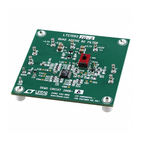
Description
Demonstration circuit DC266B-A is for the evaluation of
8th order filter circuits using an LTC1562 (no dash) and
DC266B-B for an LTC1562-2. LTC1562 and LTC1562-2
are quad 2nd order active-RC filter building blocks. The
LTC1562 or LTC1562-2 2nd order sections can be con-
figured with external resistors to implement lowpass and
narrow or wide band bandpass filters. The frequency
range for a lowpass filter is 10kHz to 150kHz and 20kHz to
300kHz for the LTC1562 and LTC1562-2 respectively. The
frequency range for a bandpass filter is 20kHz to 120kHz
and 40kHz to 250kHz for the LTC1562 and LTC1562-2
respectively (the LTC1562A is higher precision version
of the LTC1562).
For testing and evaluation, the DC266B-A is configured as
an 8th order, 50kHz bandpass filter and the DC266B-B is
configured as an 8th order, 200kHz bandpass filter.
Ltc1562 anD Ltc1562-2 BLock Diagram
+
V
5
+
V
SHUTDOWN
SWITCH
SHDN
6
R
R
15
SHUTDOWN
AGND
SWITCH
–
V
–
V
16
4
PINS 4, 7, 14
AND 17 MUST BE
7
CONNECTED TO
14
–
V
, PIN 16
17
R
IN
V
IN
Quad 2nd Order Active RC Filter IC
10
INV
9
V1
A
C
–
∫
+
D
+
∫
–
C
11
INV
12
V1
R2
R
Q
INV
V1
A
C
–
*
∫
+
2ND ORDER LOWPASS (V2) AND BANDPASS (V1)
DEMO MANUAL DC266B
LTC1562/LTC1562-2
For other possible LTC1562 or LTC1562-2 configurations,
the DC226B-A and DC226B-B have unused pads for 0805
surface mount resistors and capacitors preconfigured
with PCB traces to allow for the following filter circuits:
1. 8th order lowpass filter
2. Dual 4th or 5th order lowpass filter
3. 8th order narrow band bandpass
4. 8th order wide band bandpass.
Refer to the LTC1562 or LTC1562-2 data sheet for com-
prehensive filter design information.
Design files for this circuit board are available at
http://www.linear.com/demo/DC266B
L, LT, LTC, LTM, Linear Technology, LTspce, FilterCAD and the Linear logo are registered
trademarks of Linear Technology Corporation. All other trademarks are the property of their
respective owners.
8
V2
1
INV
2
V1
B
C
–
+
2ND ORDER SECTIONS
C
+
–
C
13
V2
20
INV
19
V1
R2
C
IN
R
Q
V
IN
V2
INV
B
C
–
*100kHz FOR
LTC1562 AND
200kHz FOR
+
LTC1562-2
2ND ORDER BANDPASS (V2) AND HIGHPASS (V1)
3
V2
∫
∫
18
V2
V1
V2
THE MAXIMUM
FREQUENCY ERROR IS
*
±0.6% FOR LTC162A,
∫
±1.0% FOR LTC1562 AND
±1.7% FOR LTC1562-2
DC266 BD
dc266bf
1
Advertisement

Related Manuals for Linear DC266B-A


Summary of Contents for Linear DC266B-A
- Page 1 8th order, 50kHz bandpass filter and the DC266B-B is L, LT, LTC, LTM, Linear Technology, LTspce, FilterCAD and the Linear logo are registered configured as an 8th order, 200kHz bandpass filter. trademarks of Linear Technology Corporation. All other trademarks are the property of their respective owners.
-
Page 2: Quick Start Procedure
See Figure 1 for proper measurement equipment setup 6. Connect an oscilloscope channel to OUT. and follow the procedure below. 7. For a DC266B-A, set the scaling of an oscilloscope to 1. Set SW1 to DUAL. 1V/20µs per division. 2. With power off, connect a dual 5V power supply to +V For a DC266B-B, set the scaling of an oscilloscope to and –V. - Page 3 DEMO MANUAL DC266B Dc266B FiLter circuits For testing and evaluation, the DC266B-A is configured The V1 diodes can be shorted out on the board if testing as an 8th order, 50kHz bandpass filter (Figure 2) and the the filter circuit with an input that saturates the output DC266B-B is configured as an 8th order, 200kHz bandpass nodes does not produce any oscillations.
- Page 4 –90 23.2k –100 20kHz 200kHz 800kHz 23.2k FREQUENCY DC266 F03a DC266 F03b 23.2k 23.2k LTC1562-2 LINEAR PHASE 8TH ORDER BPF GAIN = • RIN1 (SHORT TRANSIENT RESPONSE) 23.2k = 200kHz CENTER RIN1= –3dB BW = 40kHz GAIN 23.2k Z1B = LTC1562-2, ±1.7% 2ND ORDER FREQUENCY ERROR...
- Page 5 Information furnished by Linear Technology Corporation is believed to be accurate and reliable. However, no responsibility is assumed for its use. Linear Technology Corporation makes no representa- tion that the interconnection of its circuits as described herein will not infringe on existing patent rights.
- Page 6 Linear Technology Corporation (LTC) provides the enclosed product(s) under the following AS IS conditions: This demonstration board (DEMO BOARD) kit being sold or provided by Linear Technology is intended for use for ENGINEERING DEVELOPMENT OR EVALUATION PURPOSES ONLY and is not provided by LTC for commercial use. As such, the DEMO BOARD herein may not be complete in terms of required design-, marketing-, and/or manufacturing-related protective considerations, including but not limited to product safety measures typically found in finished commercial goods.
Need help?
Do you have a question about the DC266B-A and is the answer not in the manual?
Questions and answers