Table of Contents
Advertisement
Quick Links
Description
Demonstration Circuit 2048A is a nanopower buck-
boost DC/DC with energy harvesting battery life extender
featuring the
LTC
3330. The LTC3330 integrates a high
®
voltage energy harvesting power supply plus a DC/DC
converter powered by a primary cell battery to create a
single output supply for alternative energy applications.
The energy harvesting power supply, consisting of an
integrated low-loss full-wave bridge with a high voltage
buck converter, harvests energy from piezoelectric, solar
or magnetic sources. The primary cell input powers a
buck-boost converter capable of operating down to 1.8V
at its input. Either DC/DC converter can deliver energy to
a single output. The buck operates when harvested energy
is available, reducing the quiescent current drawn on the
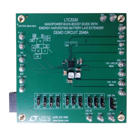
BoarD photo
Figure 1. DC2048A Demo Board
Nanopower Buck-Boost DC/DC with
Energy Harvesting Battery Life Extender
DEMO MANUAL DC2048A
battery to essentially zero. The buck-boost takes over
when harvested energy goes away.
A low noise LDO post regulator and a supercapacitor
balancer are also integrated, accommodating a wide range
of output storage configurations.
Voltage and current settings for both input and outputs
are programmable via pin-strapped logic inputs.
The LTC3330EUH is available in a 5mm × 5mm 32-lead
QFN surface mount package with exposed pad.
Design files for this circuit board are available at
http://www.linear.com/demo/DC2048A
L, LT, LTC, LTM, Linear Technology and the Linear logo are registered trademarks and Dust
is a trademark of Linear Technology Corporation. All other trademarks are the property of their
respective owners.
100
90
80
70
60
50
40
30
20
10
0
1µ
Figure 2. Typical Efficiency of DC2048A.
Buck Efficiency vs I
LTC3330EUH
V
= 1.8V
OUT
V
= 2.5V
OUT
V
= 3.3V
OUT
V
= 5V
OUT
V
= 6V, L = 22µH, DCR = 0.19
IN
10µ
100µ
1m
10m
100m
I
(A)
LOAD
DC2048A F02
LOAD
dc2048af
1
Advertisement
Table of Contents

Related Manuals for Linear DC2048A


Summary of Contents for Linear DC2048A
- Page 1 The buck operates when harvested energy is available, reducing the quiescent current drawn on the L, LT, LTC, LTM, Linear Technology and the Linear logo are registered trademarks and Dust is a trademark of Linear Technology Corporation. All other trademarks are the property of their respective owners.
-
Page 2: Performance Summary
DEMO MANUAL DC2048A performance summary Specifications are at T = 25°C SYMBOL PARAMETER CONDITIONS UNITS Input Voltage Range 18.0 Battery Voltage Range 1.8V Output Voltage Range OUT0 = 0, OUT1 = 0, OUT2 = 0 1.728 1.872 2.5V Output Voltage Range OUT0 = 1, OUT1 = 0, OUT2 = 0 2.425... -
Page 3: Operating Principle
DEMO MANUAL DC2048A operating principle rail serves as logic high for output voltage select bits UV The buck-boost uses the same hysteretic algorithm as [3:0]. The V rail is regulated at 4.8V above GND while the buck to control the output, V , with the same sleep the CAP rail is regulated at 4.8V below V... -
Page 4: Quick Start Procedure
Follow the procedure below: age to 2.0V while monitoring the input current. If the current remains less than 5mA, increase PS1 to 19V. 1. Before connecting PS1 to the DC2048A, PS1 must have Verify voltage on V is within the V 1.8V range in... - Page 5 DEMO MANUAL DC2048A Quick start proceDure 14. Add a jumper lead from V to SCAP. Verify that BAL is approximately ½ of V 15. Set JP8 to 0, JP9 to 0 and JP10 to 0 and verify that LDO_OUT is now 1.2V. Quickly remove PS1 + lead from V and verify that LDO_OUT remains at 1.2V...
- Page 6 LTC3330 and the Dust mote. input current of 300µA. On the DC2048A set JP1 to 0, JP2 to 0, JP3 to 1, JP4 to The peak power load voltage of a purely resistive source 0, JP5 to 1, JP6 to 0, JP7 to 0, JP8, JP9 and JP10 to 0, is at one half (½) of the rectified no load voltage.
- Page 7 DEMO MANUAL DC2048A connection to a Dust mote (Dc9003a-B) Figure 6 is a plot of the output power and load voltage of the V25W piezoelectric transducer into a 42.2kΩ load for various rms acceleration levels. The output power compares well with the input power that is charging C...
- Page 8 DEMO MANUAL DC2048A connection to a Dust mote (Dc9003a-B) PIEZO MIDE V25W 22µH 22µH LTC3330 22µF 1µF 4.7µF , 6.3V 100µF 180mF SCAP 2.5V 180mF 2.5V HZ202F PGVOUT 22µF EH_ON IPK2 IPK1 IPK0 OUT2 OUT1 OUT0 1µF DC2048A F08 Figure 8. LTC3330 Circuit Charging Supercapacitor at No Load without a Battery (V = 3.6V)
- Page 9 DEMO MANUAL DC2048A connection to a Dust mote (Dc9003a-B) Figure 10 shows the LTC3330 with a supercapacitor on applied, the output capacitor is depleted slightly and the the output, a battery installed and the output voltage set input capacitor must recharge the output cap. Because the to 3.6V.
- Page 10 DEMO MANUAL DC2048A connection to a Dust mote (Dc9003a-B) Figure 12 shows the LTC3330 with an output superca- of 2.5V to the energy harvester set-point of 3.6V, V pacitor, a Dust mote attached, a battery installed and EH_ON above the 2.5V PGVOUT threshold, hence, PGVOUT will connected to OUT2.
- Page 11 DEMO MANUAL DC2048A connection to a Dust mote (Dc9003a-B) While the EH_ON signal is low the buck-boost circuit on V will discharge down to the new target voltage of will consume 750nA from the battery in the sleeping 2.5V at which point the buck-boost regulator will turn on state.
- Page 12 DEMO MANUAL DC2048A connection to a Dust mote (Dc9003a-B) PIEZO MIDE V25W 22µH 22µH LTC3330 22µF 1µF = 3.6V FOR EH_ON = 1 4.7µF , 6V = 2.5V FOR EH_ON = 0 100µF SCAP SUPPLY 22µF IPK2 PGVOUT PGOOD CR2032...
-
Page 13: Parts List
DEMO MANUAL DC2048A parts list ITEM REFERENCE PART DESCRIPTION MANUFACTURER/PART NUMBER Required Circuit Components BAT1 CR2032 COIN LI-ION BATTERY DURACELL, CR2032 BTH1 SMT, CR2032 BATTERY HOLDER MPD INC, BU2032SM-HD-GCT-ND SUPERCAP, 90mF, 5.5V, 20mm × 15mm CAP-XX, HZ202F CAP, CHIP, X5R, 100µF, 20%, 10V, 1210... -
Page 14: Schematic Diagram
DEMO MANUAL DC2048A schematic Diagram dc2048af... - Page 15 Information furnished by Linear Technology Corporation is believed to be accurate and reliable. However, no responsibility is assumed for its use. Linear Technology Corporation makes no representa- tion that the interconnection of its circuits as described herein will not infringe on existing patent rights.
- Page 16 Linear Technology Corporation (LTC) provides the enclosed product(s) under the following AS IS conditions: This demonstration board (DEMO BOARD) kit being sold or provided by Linear Technology is intended for use for ENGINEERING DEVELOPMENT OR EVALUATION PURPOSES ONLY and is not provided by LTC for commercial use. As such, the DEMO BOARD herein may not be complete in terms of required design-, marketing-, and/or manufacturing-related protective considerations, including but not limited to product safety measures typically found in finished commercial goods.
Need help?
Do you have a question about the DC2048A and is the answer not in the manual?
Questions and answers