Advertisement
Quick Links
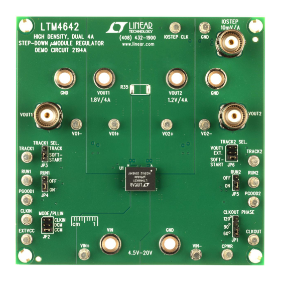
DESCRIPTION
Demonstration circuit of DC2194A features the
LTM
4642IY, the wide input voltage, high efficiency and
®
power density, dual 4A or single 8A DC/DC step-down
µModule regulator. The step-down regulator operates
from an input voltage range of 4.5V to 20V (or 2.5V min.
with 5V external bias voltage at CPWR) and provides an
adjustable output voltage range from 0.6V to 5V at 4A load
current per channel. The part is capable of operating in
dual phase single output, delivers up to 8A load current
with interleaved two phases at 180 degrees. Differential
output voltage sensing is available on Channel 1 for ap-
plications requiring more accurate output load regulation.
A user-selectable mode input is provided to allow users to
trade off ripple noise for light load efficiency: Discontinu-
ous Mode (DCM) of operation delivers higher efficiency
at light load while Continuous Conduction Mode (CCM) is
BOARD PHOTO
Arrow.com.
Downloaded from
DEMO MANUAL DC2194A
20V
, DUAL 4A or SINGLE 8A
IN
DC/DC µMODULE REGULATOR
preferred for noise sensitive applications. The mode pin
can also be used to sync the switching frequency to an
external clock. Programmable switching frequency range
is from 600kHz to 1400kHz with a ±30% synchronization
capture range. Constant on time, valley current mode
control architecture and integrated internal control loop
compensation allow very fast transient response to line
and load changes while maintaining loop stability.
It is recommended to read the data sheet and demo
manual of LTM4642 prior using or making any changes
to DC2194A.
Design files for this circuit board are available at
http://www.linear.com/demo/DC2194A
L, LT, LTC, LTM, Linear Technology and the Linear logo are registered trademarks of Linear
Technology Corporation. All other trademarks are the property of their respective owners.
LTM4642IY
dc2194afa
1
Advertisement

Related Manuals for Linear DC2194A


Summary of Contents for Linear DC2194A
- Page 1 Discontinu- ous Mode (DCM) of operation delivers higher efficiency L, LT, LTC, LTM, Linear Technology and the Linear logo are registered trademarks of Linear Technology Corporation. All other trademarks are the property of their respective owners.
-
Page 2: Performance Summary
DEMO MANUAL DC2194A PERFORMANCE SUMMARY Specifications are at T = 25°C PARAMETER CONDITIONS VALUE Dual Phase Dual Output Configuration (Default) Input Voltage Range 4.5V to 20V Input Voltage Range 2.5V to 20V (with External CPWR Bias Supply) Default Output Voltage = 4.5V to 20V 1.8V ±1.5%... - Page 3 DEMO MANUAL DC2194A PERFORMANCE SUMMARY Specifications are at T = 25°C PARAMETER CONDITIONS VALUE Dual Phase Single Output Configuration (Optional) Input Voltage Range 4.5V to 20V Input Voltage Range 2.5V to 20V (with External CPWR Bias Supply) Default Output Voltage = 4.5V to 20V 1.8V ±1.5%...
-
Page 4: Quick Start Procedure
DEMO MANUAL DC2194A QUICK START PROCEDURE Demonstration circuit DC2194A is easy to set up to evaluate probe placement technique. Short, still leads need to the performance of the LTM4642. Please refer to Figure 1 be soldered to the (+) and (–) terminals of an output for proper measurement equipment setup and follow the capacitor. - Page 5 DEMO MANUAL DC2194A QUICK START PROCEDURE – – LOAD1 LOAD2 (0A TO 4A) (0A TO 4A) – – OUT1 OUT2 – 4.5V TO 20V – – Figure 1. Proper Measurement Equipment Setup – Figure 2. Scope Probe Placement for Measuring Input or Output Voltage Ripple dc2194afa Arrow.com.
- Page 6 Table 1. Bottom Resistive Divider Values (1%) for Setting Channel 1 is configured as a master and Channel 2 is a Typical Output Voltages slave channel on DC2194A. Coincident tracking mode can be implemented by connecting TRK/SS2 of the (kΩ) 90.9 60.4...
- Page 7 CPWR is less than 5.3V, DRV Configuration: also be tied to this pin by stuffing R15 = 0Ω. Since the DC2194A can be configured as dual phase single output RUN pins of Channel 1 and Channel 2 are directly tied to to provide up to 8A total load current.
- Page 8 DEMO MANUAL DC2194A QUICK START PROCEDURE 1.0V 1.0V 1.2V 1.2V 1.5V 1.5V 1.8V 1.8V 2.5V 2.5V 3.3V 3.3V LOAD CURRENT (A) LOAD CURRENT (A) DC2194 F03 DC2194 F04 Figure 3. Measured Efficiency at 5V , 800kHz, Figure 4. Measured Efficiency at 12V...
- Page 9 DEMO MANUAL DC2194A QUICK START PROCEDURE 20MHz BWL 20MHz BWL = 27mV = 17mV O_P-P O_P-P 50mV/DIV 50mV/DIV 5µs/DIV 5µs/DIV DC2194 F08a DC2194 F08b = 800kHz = 800kHz = 12V, V = 1.8V = 12V, V = 1.2V = 4A...
- Page 10 DEMO MANUAL DC2194A QUICK START PROCEDURE = 800kHz = 800kHz = 1.8V, V = 1.2V OUT1 OUT2 = 1.8V, V = 1.2V OUT1 OUT2 = 12V, I = 4A PER PHASE LOAD = 20V, I = 4A PER PHASE LOAD TA = 25°C, NO FORCED AIRFLOW, NO HEAT SINK...
-
Page 11: Parts List
DEMO MANUAL DC2194A PARTS LIST ITEM REFERENCE PART DESCRIPTION MANUFACTURER/PART NUMBER Required Circuit Components CIN1 CAP ., ALUM. ELECT., 100µF, 25V, 7343 PANASONIC, 25SVPF100M CIN2, CIN3 CAP ., 22µF, X5R, 25V, 10%, 1206 MURATA, GRM31CR61E226KE15L COUT1, COUT4 CAP ., 22µF, X7R, 10V, 20%, 1206... -
Page 12: Schematic Diagram
DEMO MANUAL DC2194A SCHEMATIC DIAGRAM dc2194afa Arrow.com. Arrow.com. Arrow.com. Arrow.com. Arrow.com. Arrow.com. Arrow.com. Arrow.com. Arrow.com. Arrow.com. Arrow.com. Arrow.com. Downloaded from Downloaded from Downloaded from Downloaded from Downloaded from Downloaded from Downloaded from Downloaded from Downloaded from Downloaded from Downloaded from... - Page 13 Information furnished by Linear Technology Corporation is believed to be accurate and reliable. However, no responsibility is assumed for its use. Linear Technology Corporation makes no representa- tion that the interconnection of its circuits as described herein will not infringe on existing patent rights.
- Page 14 Linear Technology Corporation (LTC) provides the enclosed product(s) under the following AS IS conditions: This demonstration board (DEMO BOARD) kit being sold or provided by Linear Technology is intended for use for ENGINEERING DEVELOPMENT OR EVALUATION PURPOSES ONLY and is not provided by LTC for commercial use. As such, the DEMO BOARD herein may not be complete in terms of required design-, marketing-, and/or manufacturing-related protective considerations, including but not limited to product safety measures typically found in finished commercial goods.
Need help?
Do you have a question about the DC2194A and is the answer not in the manual?
Questions and answers