Advertisement
Quick Links
DESCRIPTION
Demonstration circuit 2721A-B features the
µModule
regulator, a tiny high performance high effi-
®
ciency step-down regulator configured as an inverting
buck-boost regulator. DC2721A-B has an operating input
voltage range of 4V to 15V and is able to provide an out-
put current of up to 3A. The output voltage can be pro-
grammed from –0.6V and –5.5V. The LTM4625EY is a
complete DC/DC point of load regulator in a thermally
PERFORMANCE SUMMARY
PARAMETER
Input Voltage Range
Output Voltage V
OUT
Maximum Continuous Output Current
Default Operating Frequency
Efficiency
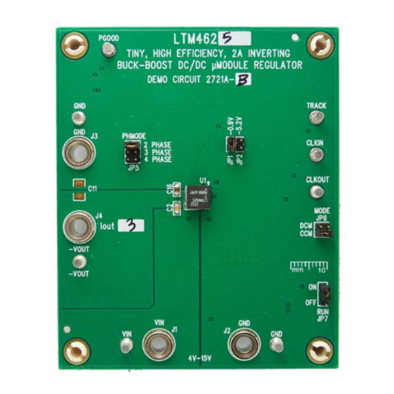
BOARD PHOTO
Tiny 3A DC/DC Inverting Buck-Boost
LTM
4625EY
enhanced 6.25mm × 6.25mm × 5.01mm BGA package
®
requiring only a few input and output capacitors. The
LTM4625 data sheet must be read in conjunction with
this demo manual for working on or modifying demo cir-
cuit 2721A-B.
Design files for this circuit board are available .
All registered trademarks and trademarks are the property of their respective owners.
Specifications are at T
CONDITIONS/NOTES
Jumper Selectable
Derating is Necessary for Certain Operating Conditions.
See Data Sheet for Details
V
= 12V, V
= –2.5V, I
= 3A
IN
OUT
OUT
DEMO MANUAL
DC2721A-B
µModule Regulator
= 25°C
A
VALUE
4V to 15V
–0.9V
, –5.2V
DC
3A
DC
1MHz
84% See Figure 2
LTM4625
DC
Rev.A
1
Advertisement

Related Manuals for Linear Analog Devices DC2721A-B


Summary of Contents for Linear Analog Devices DC2721A-B
- Page 1 DEMO MANUAL DC2721A-B LTM4625 Tiny 3A DC/DC Inverting Buck-Boost µModule Regulator DESCRIPTION Demonstration circuit 2721A-B features the 4625EY enhanced 6.25mm × 6.25mm × 5.01mm BGA package ® µModule regulator, a tiny high performance high effi- requiring only a few input and output capacitors. The ®...
-
Page 2: Quick Start Procedure
DEMO MANUAL DC2721A-B QUICK START PROCEDURE Demonstration circuit 2721A-B is an easy way to evaluate 5. Once the proper output voltage is established, adjust the performance of the LTM4625EY. Please refer to Figure the load current within the 0A to 3A range and observe 1 for test setup connections and follow the procedure the load regulation, efficiency, and other parameters. - Page 3 DEMO MANUAL DC2721A-B QUICK START PROCEDURE – LOAD 0A TO 3A – – – DC2721ab F01 – – Figure 1. Test Setup Rev.A...
- Page 4 DEMO MANUAL DC2721A-B QUICK START PROCEDURE CCM = 12V –0.9V, 1MHz –1V, 1MHz –1.5V, 1MHz –2.5V, 1MHz –3.3V, 1MHz –5.2V, 1MHz OUTPUT CURRENT (A) dc2721ab F02a CCM = 5V –0.9V, 1MHz –1V, 1MHz –1.5V, 1MHz –2.5V, 1MHz –3.3V, 1MHz –5.2V, 1MHz OUTPUT CURRENT (A) dc2721ab F02b Figure 2.
- Page 5 DEMO MANUAL DC2721A-B QUICK START PROCEDURE = 20mV/DIV = 2mV/DIV = 2A/DIV 1.5A DC OUTSTEP –0.9 1 × 100µF/6.3V + –0.9 1 × 100µF/6.3V + 1 × 22µF/6.3V + 1 × 22µF/6.3V + 1 × 47µF/6.3V 1 × 47µF/6.3V Figure 3. Measured Load Transient Response Figure 4.
-
Page 6: Parts List
DEMO MANUAL DC2721A-B PARTS LIST ITEM REFERENCE PART DESCRIPTION MANUFACTURER/PART NUMBER Required Circuit Components CAP ., 2.2uF , X5R, 10V, 10%, 0603 MURATA, GRM188R61A225KE34D CAP ., 10uF , X5R, 25V, 10%, 0805 AVX, 08053D106KAT2A CAP ., 100uF , X5R, 6.3V, 20%,1210 MURATA, GRM32ER60J107ME20L CAP ., 22uF , X5R, 6.3V, 20%, 0805 TDK, C2012X5R0J226M125AC... -
Page 7: Schematic Diagram
DEMO MANUAL DC2721A-B SCHEMATIC DIAGRAM Rev.A Information furnished by Analog Devices is believed to be accurate and reliable. However, no responsibility is assumed by Analog Devices for its use, nor for any infringements of patents or other rights of third parties that may result from its use. Specifications subject to change without notice. - Page 8 DEMO MANUAL DC2721A-B ESD Caution ESD (electrostatic discharge) sensitive device. Charged devices and circuit boards can discharge without detection. Although this product features patented or proprietary protection circuitry, damage may occur on devices subjected to high energy ESD. Therefore, proper ESD precautions should be taken to avoid performance degradation or loss of functionality. Legal Terms and Conditions By using the evaluation board discussed herein (together with any tools, components documentation or support materials, the “Evaluation Board”), you are agreeing to be bound by the terms and conditions set forth below (“Agreement”) unless you have purchased the Evaluation Board, in which case the Analog Devices Standard Terms and Conditions of Sale shall govern.
Need help?
Do you have a question about the Analog Devices DC2721A-B and is the answer not in the manual?
Questions and answers