
Related Manuals for Siemens SIPROTEC 7SD600


Summary of Contents for Siemens SIPROTEC 7SD600
- Page 1 Numerical line differential protection SIPROTEC 7SD600 V3.0 System- manual January 1999...
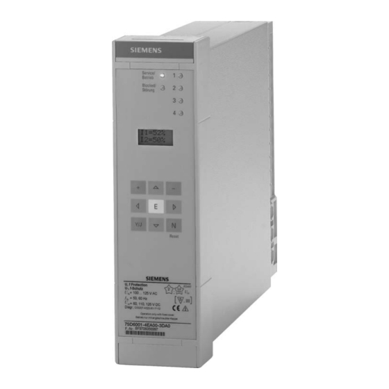
- Page 3 Numerical line differential protection SIPROTEC 7SD600 V3.0 System manual Order no. E50417-G1176-C069-A1 Figure 1 The numerical line differential protection 7SD600 January 1999 Siemens AG 1999...
- Page 4 The contents of this manual are not part of, nor do they affect, tered trademarks of their respective holder. any existing contract, commitment or legal relationship. All obligations to which Siemens is subject are detailed in the relevant sales contract which also contains the full warranty Disclaimer specifications.
- Page 5 73/23/EEC). D Only competent persons are per mitted to operate this equipment. In This conformity has been tested by SIEMENS AG in order to ensure the trouble-free and accordance with article 10 of the Directive which safe operation of this equipment, it is...
- Page 6 Siemens AG January 1999...
-
Page 7: Table Of Contents
Contents Numerical line differential protection SIPROTEC 7SD600 V3.0 System Manual Order no. E50417-G1176-C069-A1 page Introduction .............. - Page 8 Contents Numerical line differential protection SIPROTEC 7SD600 V3.0 System Manual Order no. E50417-G1176-C069-A1 page 4.4.3 Remote tripping ..............
- Page 9 Contents Numerical line differential protection SIPROTEC 7SD600 V3.0 System Manual Order no. E50417-G1176-C069-A1 page Configuring the protective functions ..........
- Page 10 Contents Numerical line differential protection SIPROTEC 7SD600 V3.0 System Manual Order no. E50417-G1176-C069-A1 page 6.6.1 General ............... . .
- Page 11 Contents Numerical line differential protection SIPROTEC 7SD600 V3.0 System Manual Order no. E50417-G1176-C069-A1 page Figures Figure 1.1 Line differential protection 7SD600 for operation with two pilot wires, block diagram 1 - 1 Figure 2.1 Dimensioned drawing of 7XP20 for panel surface mounting with terminals on the sides (dimensions in mm) .
- Page 12 Contents Numerical line differential protection SIPROTEC 7SD600 V3.0 System Manual Order no. E50417-G1176-C069-A1 page Figures Figure 6.5 Example for displaying events in the display ........
- Page 13 Contents Numerical line differential protection SIPROTEC 7SD600 V3.0 System Manual Order no. E50417-G1176-C069-A1 page Tables Table 2.1 Selection and order data ............
-
Page 14: Introduction
Introduction Numerical line differential protection SIPROTEC 7SD600 V3.0 System manual Order no. E50417-G1176-C069-A1 Introduction Application The numerical line differential protection 7SD600 is a fast and discriminative short-circuit protection for ca 7SD600 Station 1 bles and overhead lines of all voltage levels, irrespec tive of the method of neutral-point connection. -
Page 15: Features
Introduction Numerical line differential protection SIPROTEC 7SD600 V3.0 System manual Order no. E50417-G1176-C069-A1 During a system fault (short-circuit in the protected Both hardware and software are constantly monitored zone), the instantaneous values of the measured si in the device so that faults are detected and indicated gnals are stored in the device for a maximum period immediately. -
Page 16: Functional Scope
Introduction Numerical line differential protection SIPROTEC 7SD600 V3.0 System manual Order no. E50417-G1176-C069-A1 Functional scope The numerical line differential protection 7SD600 of Direct and remote tripping fers the following functions: D Tripping of local CB by external signal with settable... - Page 17 Introduction Numerical line differential protection SIPROTEC 7SD600 V3.0 System manual Order no. E50417-G1176-C069-A1 1 - 4 Siemens AG January 1999...
-
Page 18: Design
Design Numerical line differential protection SIPROTEC 7SD600 V3.0 System manual Order no. E50417-G1176-C069-A1 Design Models All protection functions, including the converter, are without ring-lugs. Only copper wires should be installed on a p.c.b. in double-height Eurocard format. used. This p.c.b., combined with a locating plate (guide rail), For dimensions, see Figure 2.1. -
Page 19: Dimensions
Design Numerical line differential protection SIPROTEC 7SD600 V3.0 System manual Order no. E50417-G1176-C069-A1 Dimensions Figures 2.1 to 2.4 show the dimensions of the diffe 7SD600K-KBKKK Housing for panel surface rent models. mounting 7XP20 with terminals on the sides. Rec. minimum distance to adjacent device 29.5... -
Page 20: Figure 2.2 Dimensioned Drawing Of 7Xp20 For Panel Surface Mounting With Terminals At Top And Bottom
Design Numerical line differential protection SIPROTEC 7SD600 V3.0 System manual Order no. E50417-G1176-C069-A1 7SD600K-KDKKK in housing for panel surface mounting 7XP20 with terminals at top and bottom Reset and scroll keys 29.5 261.5 Max. 32 terminals with a connecting cable cross-section of max. 7 mm The housing must be mounted on the control panel using studs or M6 bolts. -
Page 21: Figure 2.3 Dimensioned Drawing Of 7Xp20 For Panel Flush Mounting Or Cubicle Mounting (Dimensions In Mm)
Design Numerical line differential protection SIPROTEC 7SD600 V3.0 System manual Order no. E50417-G1176-C069-A1 7SD600K-KEKKK housing for panel flush mounting or cubicle mounting 7XP20 29.5 É É É É É É É É É É É É É É É É... -
Page 22: Summation Transformer 4Am4930
Design Numerical line differential protection SIPROTEC 7SD600 V3.0 System manual Order no. E50417-G1176-C069-A1 2.2.1 Summation transformer 4AM4930 The summation transformer 4AM4930 is equipped with screw terminals max. 2.5 mm and parallel 6.3 mm double flat spring contacts. 2 brackets are provi ded for mounting. -
Page 23: Order Data
Design Numerical line differential protection SIPROTEC 7SD600 V3.0 System manual Order no. E50417-G1176-C069-A1 Order data Table 2.1 Selection and order data Order no. 8 9 10 11 12 13 14 15 16 j - jj A 0 0 - j D A 0... -
Page 24: Technical Data
Technical data Numerical line differential protection SIPROTEC 7SD600 V3.0 System manual Order no. E50417-G1176-C069-A1 Technical data Table 3.1 General device data Current input circuits Nominal current I 20 mA without summation transformer 1 or 5 A with external summation transformer... -
Page 25: Table 3.2 Mechanical Details
Technical data Numerical line differential protection SIPROTEC 7SD600 V3.0 System manual Order no. E50417-G1176-C069-A1 Table 3.1 General device data Serial interface isolated Standard RS485 Test voltage 3.5 kV- Connections via conductor to housing terminals, two lines for data, 1 earthing cable, for connection of a PC or similar device lines must be shielded, shield must be earthed. -
Page 26: Standards And Directives
Technical data Numerical line differential protection SIPROTEC 7SD600 V3.0 System manual Order no. E50417-G1176-C069-A1 Standards and Directives Table 3.3 Electrical tests CE conformity, The product is herewith confirmed to comply with the This conformity is the result of a test carried... - Page 27 Technical data Numerical line differential protection SIPROTEC 7SD600 V3.0 System manual Order no. E50417-G1176-C069-A1 Table 3.3 Electrical tests EMC Tests on Radio Interference Voltages on Lines, only auxiliary 150 kHz to 30 MHz, Limit Class B Emitted Interference supply voltage, EN 55022, DIN VDE 0878 Part 22, IEC...
-
Page 28: Operating Conditions
Technical data Numerical line differential protection SIPROTEC 7SD600 V3.0 System manual Order no. E50417-G1176-C069-A1 Operating conditions The protection device is designed for industrial use, D Never remove or plug in individual modules when i.e. for installation in conventional relay rooms and live. -
Page 29: Line Differential Protection
Technical data Numerical line differential protection SIPROTEC 7SD600 V3.0 System manual Order no. E50417-G1176-C069-A1 Line differential protection Table 3.6 Line differential protection Setting ranges Current threshold I (release with local current) 0.00 to 1.50 (step 0.01) N line Differential current 0.05 to 2.50 (step 0.01) -
Page 30: Figure 3.1 Stabilization Characteristic Of The Differential Protection (Shown For Pre-Settings)
Technical data Numerical line differential protection SIPROTEC 7SD600 V3.0 System manual Order no. E50417-G1176-C069-A1 diff NLtg Slope Tripping Slope Ç Ç Ç Ç Ç Ç Ç Ç Ç Ç Ç Ç Ç Ç Ç Ç Ç Ç Ç Ç Setting I DIFF>... -
Page 31: Remote Tripping
Technical data Numerical line differential protection SIPROTEC 7SD600 V3.0 System manual Order no. E50417-G1176-C069-A1 Remote tripping Table 3.7 Remote tripping Tripping of the remote line end only available for devices with pilot wire monitoring Setting ranges Prolongation time for transmission to remote 0.00 to 60.00 s (step 0.01 s) -
Page 32: Summation Transformer 4Am4930
Technical data Numerical line differential protection SIPROTEC 7SD600 V3.0 System manual Order no. E50417-G1176-C069-A1 Summation transformer 4AM4930 Table 3.10 Power consumption in the current circuit for standard connection L1-L3-E (Figure 5.3) relating to through nominal current (device 7SD600 is in operation) In phase (VA) Single-phase, approx. - Page 33 Technical data Numerical line differential protection SIPROTEC 7SD600 V3.0 System manual Order no. E50417-G1176-C069-A1 3 - 10 Siemens AG January 1999...
-
Page 34: Method Of Operation
Method of operation Numerical line differential protection SIPROTEC 7SD600 V3.0 System manual Order no. E50417-G1176-C069-A1 Method of operation Overall function The numerical line differential protection 7SD600 is In the case of symmetrical nominal current flow, the equipped with a powerful 16-bit microprocessor... - Page 35 Method of operation Numerical line differential protection SIPROTEC 7SD600 V3.0 System manual Order no. E50417-G1176-C069-A1 The transformers of the measurement input group MI Binary inputs and outputs from and to the processor transform the currents I (summation current of local are controlled by the input/output modules.
-
Page 36: Summation Transformer 4Am4930
Method of operation Numerical line differential protection SIPROTEC 7SD600 V3.0 System manual Order no. E50417-G1176-C069-A1 Summation transformer 4AM4930 The summation transformer 4AM4930 combines the of 20 mA. Figure 4.2 shows the standard connection secondary currents of the main current transformer of the 4AM4930. - Page 37 Method of operation Numerical line differential protection SIPROTEC 7SD600 V3.0 System manual Order no. E50417-G1176-C069-A1 If the connection is changed so that it no longer com Figure 4.3 shows connection of the 4AM4930 to plies with Figure 4.2, it must be noted that the same...
-
Page 38: Line Differential Protection
Method of operation Numerical line differential protection SIPROTEC 7SD600 V3.0 System manual Order no. E50417-G1176-C069-A1 Line differential protection The line differential protection 7SD600 operates ac event of a short-circuit in the protected zone if the cording to the current comparison principle. To... -
Page 39: Formation Of Measured Values For Line Differential Protection With Two Pilot Wires
Method of operation Numerical line differential protection SIPROTEC 7SD600 V3.0 System manual Order no. E50417-G1176-C069-A1 4.3.3 Formation of measured values for line For the sake of simplicity, the following shall apply: differential protection with two pilot (reference resistance) wires /2 + R... -
Page 40: Measured Value Processing
Method of operation Numerical line differential protection SIPROTEC 7SD600 V3.0 System manual Order no. E50417-G1176-C069-A1 4.3.4 Measured value processing 3. Internal short-circuit, infeed from one side only: The following then applies I The differential and stabilizing current are determined = |I... -
Page 41: Additional Stabilization In The Case Of Current Transformer Saturation
Method of operation Numerical line differential protection SIPROTEC 7SD600 V3.0 System manual Order no. E50417-G1176-C069-A1 4.3.5 Additional stabilization in the case of 4.3.6 Local current threshold current transformer saturation The line differential protection 7SD600 has a local cur The saturation of the current transformer in the case rent threshold. -
Page 42: Starting, Blocking And Tripping Logic
Method of operation Numerical line differential protection SIPROTEC 7SD600 V3.0 System manual Order no. E50417-G1176-C069-A1 4.3.8 Starting, blocking and tripping logic The device is fitted with a Lockout function that can be enabled via parameter "01 L.Out". With this func... -
Page 43: Figure 4.7 Simplified Logic Diagram Of The Differential Protection
Method of operation Numerical line differential protection SIPROTEC 7SD600 V3.0 System manual Order no. E50417-G1176-C069-A1 10 DIFPRO 3015 on - off - signal only DIF.off 3003 3016 Control logic >DIF.blk DIF.blk 3017 DIF.wrk 01L.Out 01L.O.Fr to pilot wire monitoring function on-off KEY;... -
Page 44: Pilot Wire Monitoring (Optional), Transfer Tripping, Remote Tripping
Method of operation Numerical line differential protection SIPROTEC 7SD600 V3.0 System manual Order no. E50417-G1176-C069-A1 Pilot wire monitoring (optional), transfer tripping, remote tripping 4.4.1 Pilot wire monitoring In the event of a pilot wire short-circuit and through fault current (external fault), tripping may occur. This... -
Page 45: Transfer Tripping
Method of operation Numerical line differential protection SIPROTEC 7SD600 V3.0 System manual Order no. E50417-G1176-C069-A1 Station 1 Station 2 Legend: MT - Summation transformer - Transmitter (current source) - Receiver - Coupling capacitor Figure 4.8 Coupling of pilot wire monitoring 4.4.2... - Page 46 Method of operation Numerical line differential protection SIPROTEC 7SD600 V3.0 System manual Order no. E50417-G1176-C069-A1 The function "Tripping by remote station" with the transmission of a trip signal (transfer tripping or re parameters "13 TR.R" (off-on) "13 DEL" (delay time) mote tripping).
-
Page 47: Figure 4.9 Logic Diagram Of The Functions Related To The Pilot Wire Monitoring
Method of operation Numerical line differential protection SIPROTEC 7SD600 V3.0 System manual Order no. E50417-G1176-C069-A1 11 PW.MON MASTER 11 STATN SLAVE 11 DIF.BL 11T-DiBl 3371 PWM off 3372 3363 PWM blk Pilot wire monitoring >PWM bl 3376 Faul WM 12 C.PROL... -
Page 48: Additional Functions
Method of operation Numerical line differential protection SIPROTEC 7SD600 V3.0 System manual Order no. E50417-G1176-C069-A1 Additional functions The 7SD600 has the following additional functions cularly applies to failure indications such as "Failure - pilot wire monitoring" etc. D Processing of events, A green LED indicates the healthy state ("Opera... -
Page 49: Disturbance Recording
Method of operation Numerical line differential protection SIPROTEC 7SD600 V3.0 System manual Order no. E50417-G1176-C069-A1 the trip command to be recognized. The resolution of 4.5.3 Measurement of operational values the real time is 1 ms. The r.m.s. values of the currents I... -
Page 50: Software Monitoring
Method of operation Numerical line differential protection SIPROTEC 7SD600 V3.0 System manual Order no. E50417-G1176-C069-A1 D Command relay circuits 4.5.5.2 Software monitoring The command relays for operation of the trip and For continuous monitoring of the sequence of pro and close coils of the circuit-breaker are switched... - Page 51 Method of operation Numerical line differential protection SIPROTEC 7SD600 V3.0 System manual Order no. E50417-G1176-C069-A1 4 - 18 Siemens AG January 1999...
-
Page 52: Preparation Instructions
Preparation instructions Numerical line differential protection SIPROTEC 7SD600 V3.0 System manual Order no. E50417-G1176-C069-A1 Preparation instructions Warning In order to ensure the trouble-free and safe operation of this device, it must be properly transpor ted and correctly stored, assembled, operated and maintained in compliance with the warnings and instructions in the system manual. -
Page 53: Preparing For Operation
Preparation instructions Numerical line differential protection SIPROTEC 7SD600 V3.0 System manual Order no. E50417-G1176-C069-A1 Preparing for operation Please observe the operation requirements as set out 5.2.1.2 Model 7SD600K-KEKKK for panel flush in VDE 0100/ 5.73 and VDE 0105 Part 1/7.83. -
Page 54: Auxiliary Supply
Preparation instructions Numerical line differential protection SIPROTEC 7SD600 V3.0 System manual Order no. E50417-G1176-C069-A1 5.2.2.1 Auxiliary supply links must be changed. The allocation of these plug gable links to the binary inputs and their physical ar The auxiliary supply voltage has three input voltage rangement is shown in Figure 5.2. -
Page 55: Figure 5.1 Check Set Nominal Voltage Of The Integrated Power Supply
Preparation instructions Numerical line differential protection SIPROTEC 7SD600 V3.0 System manual Order no. E50417-G1176-C069-A1 Pluggable links Auxiliary nominal voltage 60 V- 220 VX 110 V- 250 VX 125 V- 110 VX X11.1 - X11.2 X11.1 - X11.2 X11.2 - X11.3 X11.2 - X11.3... -
Page 56: Figure 5.2 Check Of Selected Control Voltages Of Binary Inputs 1 To 3 On The P.c.b
Preparation instructions Numerical line differential protection SIPROTEC 7SD600 V3.0 System manual Order no. E50417-G1176-C069-A1 Binary inputs 1 Binary inputs 2 Binary inputs 3 Nominal voltages 24/48/60 V-: The pluggable links X*2 - X*3 must be inserted! (Operating point approx. 17 V-) Nominal voltages 110/125/220/250 V-: The pluggable links X*1 - X*2 can be inserted. -
Page 57: Checking The Connections
Preparation instructions Numerical line differential protection SIPROTEC 7SD600 V3.0 System manual Order no. E50417-G1176-C069-A1 5.2.3 Checking the connections D Switch off mcb for direct supply voltage. D Check trip wires to the circuit-breaker. D Check control wires to and from other devices. -
Page 58: Connection For Reduced Earth-Fault Sensitivity
Preparation instructions Numerical line differential protection SIPROTEC 7SD600 V3.0 System manual Order no. E50417-G1176-C069-A1 5.2.4.3 Connection for increased earth-fault sensitivity L1 - L3 - E If the sensitivity to single-phase earth faults must be higher than that achieved with the standard connec... -
Page 59: Different Primary Nominal Currents
Preparation instructions Numerical line differential protection SIPROTEC 7SD600 V3.0 System manual Order no. E50417-G1176-C069-A1 5.2.4.4 Different primary nominal currents If the current transformers of the two line ends have different primary nominal currents, the currents need to be matched via the matching transformer. Mat ching is carried out at the line end with the lower pri mary nominal current. -
Page 60: Demands On The Current Transformer
Preparation instructions Numerical line differential protection SIPROTEC 7SD600 V3.0 System manual Order no. E50417-G1176-C069-A1 5.2.5 Demands on the current transformer Implementation of sets of transformers with widely varying responses is not permitted, e.g. a linearized Very large short-circuit currents flowing through the... -
Page 61: Figure 5.8 Connection Of Isolating Transformer 7Xr9513
Preparation instructions Numerical line differential protection SIPROTEC 7SD600 V3.0 System manual Order no. E50417-G1176-C069-A1 both high-voltage cables and protective cable). In ad dition, the lines can be isolated via transformers, Warning which serves to sectionalize the longitudinal voltage. The induced voltage can be calculated using the follo... -
Page 62: Setting The Operator And Memory Functions
Preparation instructions Numerical line differential protection SIPROTEC 7SD600 V3.0 System manual Order no. E50417-G1176-C069-A1 Setting the operator and memory functions 5.3.1 Operating conditions In the menu items which require a code word, the and general information device is informed of the intended presetting altera tion by pressing either the "+"... - Page 63 Preparation instructions Numerical line differential protection SIPROTEC 7SD600 V3.0 System manual Order no. E50417-G1176-C069-A1 The operator interface comprises a hierarchically menu tree appears. Pressing " leads to the 2nd level structured menu tree which can be navigated using starting with the programming block (00 PRO). Re the scrolling keys A;...
-
Page 64: Figure 5.9 Excerpt From The Menu Tree: Selection Of Configuration Blocks
Preparation instructions Numerical line differential protection SIPROTEC 7SD600 V3.0 System manual Order no. E50417-G1176-C069-A1 7 S D 6 0 0 V 3 . 0 S E T T I N G S P R O 0 1 S Y S T E M D A T A INT. -
Page 65: Settings For Integrated Operation - Block 71
Preparation instructions Numerical line differential protection SIPROTEC 7SD600 V3.0 System manual Order no. E50417-G1176-C069-A1 In the following Figures this is shown in brackets next ply the new setting. The new value or text is shown. to the explanations. However, if you press the "No" key N, the change... -
Page 66: Settings For The Serial Interface - Block 72
Preparation instructions Numerical line differential protection SIPROTEC 7SD600 V3.0 System manual Order no. E50417-G1176-C069-A1 5.3.3 Settings for the serial interface - block message. Transmission gaps arise when using mo dems with data compression, error correction and differences in baud rate. If the transmission quality The device is equipped with one serial RS485 inter between modems is good, the setting 1.0 is recom... - Page 67 Preparation instructions Numerical line differential protection SIPROTEC 7SD600 V3.0 System manual Order no. E50417-G1176-C069-A1 [7208] Function type of the device in accordance with F – T Y P E VDEW/ZVEI or IEC 60870-5-103; 192 applies for the 1 9 2 differential protection.
-
Page 68: Settings For Fault Detection - Block 74
Preparation instructions Numerical line differential protection SIPROTEC 7SD600 V3.0 System manual Order no. E50417-G1176-C069-A1 5.3.4 Settings for fault detection - block 74 the drop off of the last fault detection. For the 7SD600 this is also the extent of a fault record. -
Page 69: Configuring The Protective Functions
Preparation instructions Numerical line differential protection SIPROTEC 7SD600 V3.0 System manual Order no. E50417-G1176-C069-A1 Configuring the protective functions 5.4.1 Introduction section 6.2. Alterations to the configuration parame ters require input of the code word (see section The device 7SD600 provides a range of protective 5.3.1). -
Page 70: Configuring The Functional Scope Of The Device - Block 00
Preparation instructions Numerical line differential protection SIPROTEC 7SD600 V3.0 System manual Order no. E50417-G1176-C069-A1 "No" key N, the change entered since the E key was 5.4.2 Configuring the functional scope of the last pressed is canceled and the old value or text is device - block 00 displayed. -
Page 71: Marshalling Of Binary Inputs, Binary Outputs And Displays
Preparation instructions Numerical line differential protection SIPROTEC 7SD600 V3.0 System manual Order no. E50417-G1176-C069-A1 Marshalling of binary inputs, binary outputs and displays 5.5.1 Introduction A similar situation applies to binary inputs. In this case, external information is transmitted to the device The definition of the binary inputs and outputs shown (e.g. -
Page 72: Figure 5.11Excerpt From The Menu Tree: Example For Selecting Marshalling Of Binary Inputs
Preparation instructions Numerical line differential protection SIPROTEC 7SD600 V3.0 System manual Order no. E50417-G1176-C069-A1 7 S D 6 0 0 V 3 . 0 S E T C O N R O U T R O U T R O U T... -
Page 73: Marshalling Of The Binary Inputs - Block 61
Preparation instructions Numerical line differential protection SIPROTEC 7SD600 V3.0 System manual Order no. E50417-G1176-C069-A1 The required function is confirmed with the enter key 5.5.2 Marshalling of the binary inputs E. Additional functions (under further index numbers) - block 61 can then be selected for the same physical module The device has 3 binary inputs which are designated using the B key. -
Page 74: Table 5.1 Marshallable Binary Input Functions
Preparation instructions Numerical line differential protection SIPROTEC 7SD600 V3.0 System manual Order no. E50417-G1176-C069-A1 [6100] Beginning of the block "Marshalling of binary inputs" R O U T " Use the " key to go to the first binary input: [6101]... -
Page 75: Marshalling Of Signal Relay - Block 62
Preparation instructions Numerical line differential protection SIPROTEC 7SD600 V3.0 System manual Order no. E50417-G1176-C069-A1 An overview of the factory settings for the binary in puts is provided in table 5.2. Table 5.2 Factory set binary inputs 4th operating level 5th operating level Fno. - Page 76 Preparation instructions Numerical line differential protection SIPROTEC 7SD600 V3.0 System manual Order no. E50417-G1176-C069-A1 Switch to the selection level with the "key: [6223] Signal relay 2 has the following factory setting: S R 2 Fault in the pilot wire connection (if pilot wire monito...
-
Page 77: Marshalling Of The Leds - Block 63
Preparation instructions Numerical line differential protection SIPROTEC 7SD600 V3.0 System manual Order no. E50417-G1176-C069-A1 Table 5.3 Marshallable binary output functions Fno. Short text Logical function (display on LCD) 3346 Off.Rem.Tr Trip from remote station: trip 3347 Off.Rem.off Trip from remote station: trip command 3348 Off.Rec... -
Page 78: Table 5.5 Factory Set Leds
Preparation instructions Numerical line differential protection SIPROTEC 7SD600 V3.0 System manual Order no. E50417-G1176-C069-A1 [6300] Beginning of the blocks "Marshalling of the LEDs" M A R S H " L E D Use the " key to go to the first marshallable LED:... -
Page 79: Marshalling Of The Command Relays - Block 64
Preparation instructions Numerical line differential protection SIPROTEC 7SD600 V3.0 System manual Order no. E50417-G1176-C069-A1 5.5.5 Marshalling of the command relays - All indications shown in table 5.3 can be marshalled block 64 to command relays. Command functions have no ef... -
Page 80: Table 5.6 Factory Set Command Functions
Preparation instructions Numerical line differential protection SIPROTEC 7SD600 V3.0 System manual Order no. E50417-G1176-C069-A1 The "+" key lets you display all marshallable output command relay 1 using the B key. Each selection functions once the code word has been entered. The must be confirmed with the E key. - Page 81 Preparation instructions Numerical line differential protection SIPROTEC 7SD600 V3.0 System manual Order no. E50417-G1176-C069-A1 5 - 30 Siemens AG January 1999...
-
Page 82: Operating Instructions
Operating instructions Numerical line differential protection SIPROTEC 7SD600 V3.0 System manual Order no. E50417-G1176-C069-A1 Operating instructions Safety measures Warning The safety regulations applicable to working in power plants must be observed for testing and commissioning. Caution Operating the device on a battery charger without a battery connected can lead to unacceptably high voltages and to destruction of the device. -
Page 83: Operation With A Pc
Operating instructions Numerical line differential protection SIPROTEC 7SD600 V3.0 System manual Order no. E50417-G1176-C069-A1 Keys for scrolling in the display 6.2.2 Operation with a PC Scroll forwards: the next operating posi A PC (with MS WINDOWS operating system) and the... -
Page 84: Front View Of The Device
Operating instructions Numerical line differential protection SIPROTEC 7SD600 V3.0 System manual Order no. E50417-G1176-C069-A1 6.2.4 Front view of the device In service indication (green) Service/ Operation Fault indication (red) Blocked/ Fault LED indication 1 to 4 (red), marshallable (factory setting, see below) -
Page 85: Setting Of Function Parameters
Operating instructions Numerical line differential protection SIPROTEC 7SD600 V3.0 System manual Order no. E50417-G1176-C069-A1 Setting of function parameters 6.3.1 Introduction The parameter blocks are reached by pressing the B key. Block 01 with the "NETWORK and station 6.3.1.1 Procedure for parameterization DATA"... - Page 86 Operating instructions Numerical line differential protection SIPROTEC 7SD600 V3.0 System manual Order no. E50417-G1176-C069-A1 The code word must be entered to set the function D Setting addresses with text parameters parameters (see 5.3.1). Without the code word, the The display shows the two-digit block number and settings can be read but not changed.
-
Page 87: Setting Date And Time
Operating instructions Numerical line differential protection SIPROTEC 7SD600 V3.0 System manual Order no. E50417-G1176-C069-A1 immediately become valid and are permanently sto No code word is necessary to change the date and red in non-volatile EEPROMs. time. The day, month and year are set by pressing the "+"... -
Page 88: Initial Display
Operating instructions Numerical line differential protection SIPROTEC 7SD600 V3.0 System manual Order no. E50417-G1176-C069-A1 [8102] A new date can now be entered. This is done in the D A T E order: day, month, year DD " MM " YY 2 7 . -
Page 89: System And Station Data - Block 01
Operating instructions Numerical line differential protection SIPROTEC 7SD600 V3.0 System manual Order no. E50417-G1176-C069-A1 6.3.3 System and station data - Block 01 The device requires some system and station data. [1100] Start of the block "System data" S Y S T E M "... - Page 90 Operating instructions Numerical line differential protection SIPROTEC 7SD600 V3.0 System manual Order no. E50417-G1176-C069-A1 [1102] Primary rated current of the protected plant (of the line) 1 0 0 0 smallest setting value: ... .
-
Page 91: Settings For The Line Differential Protection
Operating instructions Numerical line differential protection SIPROTEC 7SD600 V3.0 System manual Order no. E50417-G1176-C069-A1 [1136] Resetting the Lockout function: L . O . F r with LED acknowledge key; K E Y via binary input; with LED acknowledge key or binary input K E Y 6.3.4... -
Page 92: Figure 6.3 Trip Characteristic Of The 7Sd600
Operating instructions Numerical line differential protection SIPROTEC 7SD600 V3.0 System manual Order no. E50417-G1176-C069-A1 I DIFF> (Adr. 10 I-DIF>) is the pick-up threshold for the protection, practically only occur in cables. Cur the differential current. This is the total current mea rent differences (i.e. - Page 93 Operating instructions Numerical line differential protection SIPROTEC 7SD600 V3.0 System manual Order no. E50417-G1176-C069-A1 In cases in which a transformer is directly connected Excceding the limit leads to blocking of the differential to a line, i.e. without current transformer and circuit- protection.
- Page 94 Operating instructions Numerical line differential protection SIPROTEC 7SD600 V3.0 System manual Order no. E50417-G1176-C069-A1 In special applications it may be of advantage to delay set for this (addr. 10 T delay). the trip command of the protection slightly (e.g. for This is normally set to 0.
-
Page 95: Settings For The Pilot Wire Monitoring
Operating instructions Numerical line differential protection SIPROTEC 7SD600 V3.0 System manual Order no. E50417-G1176-C069-A1 A current threshold can be set for blocking by the dif value for this differential current can be calculated ferential current monitoring function ("Spill current") with the following equation: (addr. -
Page 96: Settings For The Remote Tripping
Operating instructions Numerical line differential protection SIPROTEC 7SD600 V3.0 System manual Order no. E50417-G1176-C069-A1 [1600] Start of the block "Pilot wire monitoring" 1 1 P I L O T " W I R E S U P . [1601] Pilot wire monitoring P W . -
Page 97: Settings For Tripping On Receiving Remote Command
Operating instructions Numerical line differential protection SIPROTEC 7SD600 V3.0 System manual Order no. E50417-G1176-C069-A1 [2200] Start of the block "Inter trip by binary input" I N T E R T R I P . [2203] Prolongation time for sending the remote trip signal to S . -
Page 98: Events (Alarms)
Operating instructions Numerical line differential protection SIPROTEC 7SD600 V3.0 System manual Order no. E50417-G1176-C069-A1 Events (alarms) 6.4.1 Introduction With the " key, the next operating level may be re ached and all message blocks can be accessed there Following system disturbances, the recorded events one after the other. -
Page 99: Figure 6.4 Selection Of The Event Blocks
Operating instructions Numerical line differential protection SIPROTEC 7SD600 V3.0 System manual Order no. E50417-G1176-C069-A1 7 S D 6 0 0 V 3 . 0 S E T T I N G RESET E V E N T (single events) E V E N T... -
Page 100: Operational Events - Block 81
Operating instructions Numerical line differential protection SIPROTEC 7SD600 V3.0 System manual Order no. E50417-G1176-C069-A1 6.4.2 Operational events - Block 81 It is not necessary to enter the code word. After se lecting block 81 the operational events appear. All the Operational events are information which the device available operational events are displayed below. - Page 101 Operating instructions Numerical line differential protection SIPROTEC 7SD600 V3.0 System manual Order no. E50417-G1176-C069-A1 Direct feedbacks of Binary inputs CB auxiliary contact, all poles closed (K/G) > CB o n Blocking DIFF protective function (K/G) > D I F b l k...
- Page 102 Operating instructions Numerical line differential protection SIPROTEC 7SD600 V3.0 System manual Order no. E50417-G1176-C069-A1 Differential protection in service (K/G) D I F . s e r v. Blocking by DIFF current trip (K/G) B . D I F Lockout state of trip command...
-
Page 103: Fault Events - Block 82
Operating instructions Numerical line differential protection SIPROTEC 7SD600 V3.0 System manual Order no. E50417-G1176-C069-A1 6.4.3 Fault events - Block 82 A system disturbance is defined such that a primary system fault is treated as a single system disturbance The events of the last 8 system disturbances can be up to its ultimate clearance. - Page 104 Operating instructions Numerical line differential protection SIPROTEC 7SD600 V3.0 System manual Order no. E50417-G1176-C069-A1 1st line Fault number 2nd line: Start of the relative time Start of relative time Event that started the relative time D e v . A c t .
- Page 105 Operating instructions Numerical line differential protection SIPROTEC 7SD600 V3.0 System manual Order no. E50417-G1176-C069-A1 Fault events of the Remote TRIP function Transfer trip signal is being sent (K/G) T R A N . s e n TRIP by remote station: Starting (K/G) R e c .
-
Page 106: Reading Out Operational Measured Values - Block 84
Operating instructions Numerical line differential protection SIPROTEC 7SD600 V3.0 System manual Order no. E50417-G1176-C069-A1 6.4.4 Reading out operational measured va the sub-level with the "key. There is no need to en lues - Block 84 ter a code word. The values are displayed in percent of the rated varia Operational measured values can be displayed in bles. -
Page 107: Operational Control Capabilities
Operating instructions Numerical line differential protection SIPROTEC 7SD600 V3.0 System manual Order no. E50417-G1176-C069-A1 Operational control capabilities During operation of the device, interventions are pos nected to binary inputs when the device is installed sible with which individual functions and indications (cf. - Page 108 Operating instructions Numerical line differential protection SIPROTEC 7SD600 V3.0 System manual Order no. E50417-G1176-C069-A1 [8101] First the "current" date (DD. MM.YY) and the curernt 0 1 . 0 1 . 9 9 time (HH:MM:SS)are displayed. The actual setting 0 1 : 1 5 : 0 6 blocks may be reached with B.
-
Page 109: Testing And Commissioning
Operating instructions Numerical line differential protection SIPROTEC 7SD600 V3.0 System manual Order no. E50417-G1176-C069-A1 Testing and commissioning 6.6.1 General Danger Before commissioning, the preparations for putting the device into service as stipulated in chapter 5 must The secondary connections of the be completed. -
Page 110: Checking The Line Differential Protection
Operating instructions Numerical line differential protection SIPROTEC 7SD600 V3.0 System manual Order no. E50417-G1176-C069-A1 It is important for all tests that the appropriate indica Symmetrical three-phase test current and standard tions are given by the LEDs and by the signal relays connection of the summation transformer according for remote signaling. - Page 111 Operating instructions Numerical line differential protection SIPROTEC 7SD600 V3.0 System manual Order no. E50417-G1176-C069-A1 When using single-phase current injection, and a win ding factor which is greater than 1, the thermally per missible current is reduced by the factor N...
-
Page 112: Commissioning With Primary Measured Signals
Operating instructions Numerical line differential protection SIPROTEC 7SD600 V3.0 System manual Order no. E50417-G1176-C069-A1 Commissioning with primary measured signals Before the line is energized, all secondary testing D Protective function IND ONLY The protective func equipment must be removed. The preparations for tion operates and outputs indications. - Page 113 Operating instructions Numerical line differential protection SIPROTEC 7SD600 V3.0 System manual Order no. E50417-G1176-C069-A1 Changing to the next block with " leads to the block Changing again with " leads to testing the switching Testing the switching states of the inputs/outputs.
- Page 114 Operating instructions Numerical line differential protection SIPROTEC 7SD600 V3.0 System manual Order no. E50417-G1176-C069-A1 [4102] Block "Testing the switching states of the relays" T E S T After confirming with the Enter key E a question is S T A T E asked which can be answered with Yes or No.
-
Page 115: Measuring And Setting The Pilot Wire Resistance
Operating instructions Numerical line differential protection SIPROTEC 7SD600 V3.0 System manual Order no. E50417-G1176-C069-A1 6.7.2 Measuring and setting the To execute the pilot wire resistance measurement, pilot wire resistance the two 7SD600 relays must be connected to the pi lot wire pair at their respective line ends. - Page 116 Operating instructions Numerical line differential protection SIPROTEC 7SD600 V3.0 System manual Order no. E50417-G1176-C069-A1 Display of the measured pilot wire resistance (resolution 1 W, e.g. 566 W) C O M – R x 5 6 6 Detector picked up F A U L T...
-
Page 117: Checking The Current Transformer Termination
Operating instructions Numerical line differential protection SIPROTEC 7SD600 V3.0 System manual Order no. E50417-G1176-C069-A1 6.7.3 Checking the Table 6.2 Measured currents with incorrect current transformer termination CT connection measured possible correction error The current transformer termination is checked with I1/I expected primary measured signals. -
Page 118: Trip Test With The Circuit-Breaker
Operating instructions Numerical line differential protection SIPROTEC 7SD600 V3.0 System manual Order no. E50417-G1176-C069-A1 The current value I1 read out is now about 2.65 times 6.7.4 Trip test with the circuit-breaker the current value in the symmetrical test. The pilot wire protection 7SD600 allows simple te If the measured current practically does not change in sting of the circuit-breaker. - Page 119 Operating instructions Numerical line differential protection SIPROTEC 7SD600 V3.0 System manual Order no. E50417-G1176-C069-A1 [4400] Block "Circuit-breaker test tripping" T E S T " O F F [4404] After confirming with the Enter key E a prompt to T E S T enter the code word appears.
-
Page 120: Checking The Direct And Remote Tripping (If Available)
Operating instructions Numerical line differential protection SIPROTEC 7SD600 V3.0 System manual Order no. E50417-G1176-C069-A1 6.7.5 Checking the direct and remote tripping 6.7.6 Resetting the Lockout state (if available) When the Lockout function is switched on, this func If remote tripping by binary input is used, these func tion can be reset with the keypad or with DIGSI even tions must also be checked. -
Page 121: Putting The Protection Into Service
Operating instructions Numerical line differential protection SIPROTEC 7SD600 V3.0 System manual Order no. E50417-G1176-C069-A1 Putting the protection into service Check that the module is inserted properly and scre The setting values should be re-checked if they were wed in tightly. The green LED "Operation" must be changed during the test. - Page 122 Operating instructions Numerical line differential protection SIPROTEC 7SD600 V3.0 System manual Order no. E50417-G1176-C069-A1 6 - 41 Siemens AG January 1999...
-
Page 124: Maintenance And Troubleshooting
Maintenance and Troubleshooting Numerical line differential protection SIPROTEC 7SD600 V3.0 System manual Order no. E50417-G1176-C069-A1 Maintenance and Troubleshooting Digital protection equipment has no special mainte grammed) drops out and signals the error with its nance requirements. All measuring and signal proces NCC. -
Page 125: Troubleshooting
Maintenance and Troubleshooting Numerical line differential protection SIPROTEC 7SD600 V3.0 System manual Order no. E50417-G1176-C069-A1 Troubleshooting If the device reports a failure, the following procedure is recommended. Warning If none of the LEDs on the device's front panel light up, check:... - Page 126 Maintenance and Troubleshooting Numerical line differential protection SIPROTEC 7SD600 V3.0 System manual Order no. E50417-G1176-C069-A1 Fuse of the power supply; slow-blow (T) Rated current/ at U Code letter Front with 24/48 V- 1.6 / 250 G View of the circuit board of...
- Page 127 Maintenance and Troubleshooting Numerical line differential protection SIPROTEC 7SD600 V3.0 System manual Order no. E50417-G1176-C069-A1 7 - 4 Siemens AG January 1999...
-
Page 128: Repairs
Repairs Numerical line differential protection SIPROTEC 7SD600 V3.0 System manual Order no. E50417-G1176-C069-A1 Repairs It is strongly recommend not to repair defective devi ces or modules because specially selected electronic Caution components are used which must be handled in ac cordance with the directives for ESD (Electrostatical lySensitive Devices). - Page 129 Repairs Numerical line differential protection SIPROTEC 7SD600 V3.0 System manual Order no. E50417-G1176-C069-A1 8 - 2 Siemens AG January 1999...
-
Page 130: Storage
Storage Numerical line differential protection SIPROTEC 7SD600 V3.0 System manual Order no. E50417-G1176-C069-A1 Storage The devices must be stored in dry, clean rooms. The Approximately every two years, it is recommended to temperature range -25 to +55 _C (see chapter 3 un... - Page 131 Storage Numerical line differential protection SIPROTEC 7SD600 V3.0 System manual Order no. E50417-G1176-C069-A1 9 - 2 Siemens AG January 1999...
- Page 132 Surface mounting case, lateral terminals, SURFACE MOUNTING CASE 7SD600*-*BA00-*DA0 Flush mounting case / FLUSH MOUNTING CASE 7SD600*-*EA00-*DA0 Hilfsadernanschluß/ PILOT WIRE TERMINALS LED2 KOMMANDORELAIS/COMMAND RELAYS (-K5) K1: AUS-Kommando/TRIP-COMMAND EINGABE/INPUT (-K6) Diff blo Kdo/DIFF BLO -BI1 K2: AUS-Kommando/TRIP-COMMAND (-K8) Lockout Quitt/LOCKOUT RESET -BI2 MELDERELAIS/SIGNAL RELAY LED-Quit/LED-RESET...
-
Page 133: Connection Diagrams
Appendix Numerical line differential protection SIPROTEC 7SD600 V3.0 System manual Order no. E50417-G1176-C069-A1 Connection diagrams Caution! The pilot wires may neither be earthed nor equipped with surge arresters. 7SD600 Summation transformer 4AM4930 Bridged terminals: D-G; B-E Figure A1 Standard connection L1-L3-E, suitable for all networks... -
Page 134: Figure A1 Connection L1-L2-L3 With Reduced Earth-Fault Sensitivity, Preferable For Effectively Earthed Networks With Particularly Low Zero Sequence Impedance
Appendix Numerical line differential protection SIPROTEC 7SD600 V3.0 System manual Order no. E50417-G1176-C069-A1 Caution! The pilot wires may neither be earthed nor equipped with surge arresters. 7SD600 Summation transformer 4AM4930 Bridged terminals: D-G; Figure A1 Connection L1-L2-L3 with reduced earth-fault sensitivity,... -
Page 135: Figure A1 Connection L1-L3-E With Increased Earth-Fault Sensitivity, Preferable For Low Resistance Earthed Networks
Appendix Numerical line differential protection SIPROTEC 7SD600 V3.0 System manual Order no. E50417-G1176-C069-A1 Caution! The pilot wires may neither be earthed nor equipped with surge arresters. 7SD600 Summation transformer 4AM4930 Bridged terminals: D-G; Figure A1 Connection L1-L3-E with increased earth-fault sensitivity, preferable for low resistance earthed networks... -
Page 136: Figure A1 Adaptation Of Unequal Primary Currents, Example With Standard Connection L1-L3-E
Appendix Numerical line differential protection SIPROTEC 7SD600 V3.0 System manual Order no. E50417-G1176-C069-A1 Caution! The pilot wires may neither be earthed nor equipped with surge arresters. 7SD600 Summation transformer 4AM4930 Bridged terminals: D-G; Figure A1 Adaptation of unequal primary currents, example with standard connection L1-L3-E... -
Page 137: Figure A1 Connection To Two Current Transformers L1-L3, Only For Insulated Or Resonant-Earthed Networks
Appendix Numerical line differential protection SIPROTEC 7SD600 V3.0 System manual Order no. E50417-G1176-C069-A1 Caution! The pilot wires may neither be earthed nor equipped with surge arresters. 7SD600 Summation transformer 4AM4930 Bridged terminals: D-G; Figure A1 Connection to two current transformers L1-L3, only for insulated or resonant-earthed networks... -
Page 138: Menu Tree, Tables
Appendix Numerical line differential protection SIPROTEC 7SD600 V3.0 System manual Order no. E50417-G1176-C069-A1 Menu tree, Tables 7SD600 7SD600 Ã V3.00 SETTING 00 PRO 00PW.MON Ã 01 NET 01 Netwf DATA 01IN Ln 01IW PRI 01Rx 01 TAUSK 01 L.Out 01L.O.En... - Page 139 Appendix Numerical line differential protection SIPROTEC 7SD600 V3.0 System manual Order no. E50417-G1176-C069-A1 10 T–SpC 11PILOT 11PW.MON WIRE MON 11STATN. 11DIF.BL 11T–DiBl 12REMOTE 12S.EXT Â TRIP Â 13TRIP. 13TRI.R. REM ST. 13DELAY 13EXT 60 MARSH 61 MARSH 61 MARSH 61 BI1 1 Ã...
- Page 140 Appendix Numerical line differential protection SIPROTEC 7SD600 V3.0 System manual Order no. E50417-G1176-C069-A1 62 MARSH 62SR3 1 SR 3 62SR3 20 63 MARSH 63 MARSH 63ED1 1 LED 1 63LE1 20 63 MARSH 63LED2 1 LED 2 63LE2 20 63 MARSH...
- Page 141 Appendix Numerical line differential protection SIPROTEC 7SD600 V3.0 System manual Order no. E50417-G1176-C069-A1 72 F–TYPE 72 PC–IN 72GAP 72 BAUD 72 PARIT 74 STO 74 STO F MEM. 74 T MAX 74 T LEAD 74 T FOL 5 SYST 95 TEST Ã...
- Page 142 Appendix Numerical line differential protection SIPROTEC 7SD600 V3.0 System manual Order no. E50417-G1176-C069-A1 82 71 SF INDICATION 82 81 SF INDICATION 84 OP. MEAS V. ADD. DATE DATE FCT. TIME TIME DATE TIME TESTS TST I/O TEST BI STATE TEST BI...
- Page 143 Appendix Numerical line differential protection SIPROTEC 7SD600 V3.0 System manual Order no. E50417-G1176-C069-A1 Information table for function parameters 7SD600 SETT. – parameter block processing 00 PRO – device scope 00 PW.MON No.AVAI. Configure pilot wire monitoring AVAIL. not available available 01 SYSTEM DATA –...
- Page 144 Appendix Numerical line differential protection SIPROTEC 7SD600 V3.0 System manual Order no. E50417-G1176-C069-A1 10 T DELAY delay time for the trip min. 0.00 max. 60.00 –––– 10 2HARM blocking with 2nd harmonic on/off 10 Harm2% 2nd harmon. component in diff.
- Page 145 Appendix Numerical line differential protection SIPROTEC 7SD600 V3.0 System manual Order no. E50417-G1176-C069-A1 13 TRIP BY REM STN. – tripping by remote station 13 TRIP.R. status of TRIP by remote station 13 DEL. delay time for TRIP by remote station min.
- Page 146 Appendix Numerical line differential protection SIPROTEC 7SD600 V3.0 System manual Order no. E50417-G1176-C069-A1 Information table for configuration parameters 7SD600 MARSH marshallings Marsh BI – marshalling binary inputs Marsh BI1 – marshalling binary input 1 61 BI1 1 binary input 1 indication 1...
- Page 147 Appendix Numerical line differential protection SIPROTEC 7SD600 V3.0 System manual Order no. E50417-G1176-C069-A1 61 BI2 3 binary input 2 indication 3 61 BI2 4 binary input 2 indication 4 61 BI2 5 binary input 2 indication 5 61 BI2 6...
- Page 148 Appendix Numerical line differential protection SIPROTEC 7SD600 V3.0 System manual Order no. E50417-G1176-C069-A1 61 BI3 7 binary input 3 indication 7 61 BI3 8 binary input 3 indication 8 61 BI3 9 binary input 3 indication 9 61 B3 10 binary input 3 indication 10 Marsh SR –...
- Page 149 Appendix Numerical line differential protection SIPROTEC 7SD600 V3.0 System manual Order no. E50417-G1176-C069-A1 62 SR2 11 signal relay 2 indication 11 62 SR2 12 signal relay 2 indication 12 62 SR2 13 signal relay 2 indication 13 62 SR2 14...
- Page 150 Appendix Numerical line differential protection SIPROTEC 7SD600 V3.0 System manual Order no. E50417-G1176-C069-A1 62 SR3 5 signal relay 3 indication 5 62 SR3 6 signal relay 3 indication 6 62 SR3 7 signal relay 3 indication 7 62 SR3 8...
- Page 151 Appendix Numerical line differential protection SIPROTEC 7SD600 V3.0 System manual Order no. E50417-G1176-C069-A1 62 SR3 20 signal relay 3 indication 20 Marsh LED – marshalling LED’s Marsh LED 1 – marshalling LED 1 63 LED1 1 LED 1 indication 1...
- Page 152 Appendix Numerical line differential protection SIPROTEC 7SD600 V3.0 System manual Order no. E50417-G1176-C069-A1 63 LE1 14 LED 1 indication 14 63 LE1 15 LED 1 indication 15 63 LE1 16 LED 1 indication 16 63 LE1 17 LED 1 indication 17...
- Page 153 Appendix Numerical line differential protection SIPROTEC 7SD600 V3.0 System manual Order no. E50417-G1176-C069-A1 63 LED2 8 LED 2 indication 8 63 LED2 9 LED 2 indication 9 63 LE2 10 LED 2 indication 10 63 LE2 11 LED 2 indication 11...
- Page 154 Appendix Numerical line differential protection SIPROTEC 7SD600 V3.0 System manual Order no. E50417-G1176-C069-A1 Marsh LED 3 – marshalling LED 3 63 LED3 1 LED 3 indication 1 63 LED3 2 LED 3 indication 2 63 LED3 3 LED 3 indication 3...
- Page 155 Appendix Numerical line differential protection SIPROTEC 7SD600 V3.0 System manual Order no. E50417-G1176-C069-A1 63 LE3 15 LED 3 indication 15 63 LE3 16 LED 3 indication 16 63 LE3 17 LED 3 indication 17 63 LE3 18 LED 3 indication 18...
- Page 156 Appendix Numerical line differential protection SIPROTEC 7SD600 V3.0 System manual Order no. E50417-G1176-C069-A1 63 LED4 9 LED 4 indication 9 63 LE4 10 LED 4 indication 10 63 LE4 11 LED 4 indication 11 63 LE4 12 LED 4 indication 12...
- Page 157 Appendix Numerical line differential protection SIPROTEC 7SD600 V3.0 System manual Order no. E50417-G1176-C069-A1 64 CR1 3 command relay 1 indication 3 64 CR1 4 command relay 1 indication 4 64 CR1 5 command relay 1 indication 5 64 CR1 6...
- Page 158 Appendix Numerical line differential protection SIPROTEC 7SD600 V3.0 System manual Order no. E50417-G1176-C069-A1 64 CR1 18 command relay 1 indication 18 64 CR1 19 command relay 1 indication 19 64 CR1 20 command relay 1 indication 20 Marsh CR 2 – marshalling command relay 2...
- Page 159 Appendix Numerical line differential protection SIPROTEC 7SD600 V3.0 System manual Order no. E50417-G1176-C069-A1 64 CR2 12 command relay 2 indication 12 64 CR2 13 command relay 2 indication 13 64 CR2 14 command relay 2 indication 14 64 CR2 15...
- Page 160 Appendix Numerical line differential protection SIPROTEC 7SD600 V3.0 System manual Order no. E50417-G1176-C069-A1 72 F–TYPE function type (for VDEW interface) min. 1 max. 254 –––– 72 PC–IN functional scope of the PC interface DIGSI V3 DIGSI V3 ASCII ASCII VDEW–com VDEW–compatible...
- Page 161 Appendix Numerical line differential protection SIPROTEC 7SD600 V3.0 System manual Order no. E50417-G1176-C069-A1 Indications of the 7SD600 for PC, LC–display and Binary inputs/outputs ––––––––––––––––––––––––––––––––––––––––––––––––––––––––––––––––– FNo. – function number of the event Op/Flt – operational/fault event K/KG: coming/coming and going event...
- Page 162 Appendix Numerical line differential protection SIPROTEC 7SD600 V3.0 System manual Order no. E50417-G1176-C069-A1 |FNo.|Text | Meaning |Op|Flt|I|O| + + | |3303|>RT blk | >blocking of the remote trip |I|O| |3306|>R–TRIP | >remote trip of the remote station |I|O| |3312|RT blk.
-
Page 163: Detailed Calculation Of The Current Transformer Requirements
Appendix Numerical line differential protection SIPROTEC 7SD600 V3.0 System manual Order no. E50417-G1176-C069-A1 Detailed calculation of the current transformer requirements Both conditions 1. and 2. (see section 5.2.5) must be exceeds the tripping value according to the stabiliza satisfied. Current transformer minimum data: 10P10. - Page 164 Appendix Numerical line differential protection SIPROTEC 7SD600 V3.0 System manual Order no. E50417-G1176-C069-A1 The operational accuracy limit factor for the respec Rated burden of the current transformer tive line end must be calculated with formula 1. The = 20 VA...
- Page 165 Appendix Numerical line differential protection SIPROTEC 7SD600 V3.0 System manual Order no. E50417-G1176-C069-A1 A - 34 Siemens AG January 1999...
- Page 166 INDEX Numerical line differential protection SIPROTEC 7SD600 V3.0 System manual Order no. E50417-G1176-C069-A1 with reduced earth-fault sensitivity, A - 3 Control capabilities, 6 - 26 additional functions, 4 - 15 control voltage for binary inputs, 5 - 3 binary outputs, 4 - 15...
- Page 167 INDEX Numerical line differential protection SIPROTEC 7SD600 V3.0 System manual Order no. E50417-G1176-C069-A1 Menu tree, A - 7 method of operation, 4 - 1 general device data, 3 - 1 overall function, 4 - 1 models, 2 - 1 monitoring functions, 4 - 16, 6 - 20...
- Page 168 INDEX Numerical line differential protection SIPROTEC 7SD600 V3.0 System manual Order no. E50417-G1176-C069-A1 Remote tripping, 6 - 15, 6 - 21 tripping logic, 4 - 9 remote tripping, 3 - 8, 4 - 12 Troubleshooting, 7 - 2 Repairs, 8 - 1...
- Page 169 Further more, we always welcome any suggestions or propo Phone/Fax sals for improvement. Suggestions Printing Corrections Order no. Edition 7SD600 E50417-G1176-C069-A1 January 1999 Numerical line differential protection SIPROTEC 7SD600 V3.0 System manual...
- Page 170 Department of Power Transmission and Distribution Operational sector: Secondary Systems Postfach 48 06 D 90026 Nuremberg Siemens Aktiengesellschaft Order no. E50417-G1176-C069-A1 Reference number: 7SD600 V3.0 Printed in Germany...
Need help?
Do you have a question about the SIPROTEC 7SD600 and is the answer not in the manual?
Questions and answers