Siemens Reyrolle 7SR5 Manual
Hide thumbs
Also See for Reyrolle 7SR5:
- Manual (504 pages) ,
- Operating manual (146 pages) ,
- Device manual (556 pages)

Related Manuals for Siemens Reyrolle 7SR5


Summary of Contents for Siemens Reyrolle 7SR5
- Page 1 Preface Open Source Software Table of Contents Reyrolle 7SR5 Introduction Hardware Devices and Front Fascia Panels Device Modules V01.00 Working with the Device Manual Technical Data C53000-T7040-C013-1...
- Page 2 Disclaimer of Liability Copyright Subject to changes and errors. The information given in Copyright © Siemens 2019. All rights reserved. this document only contains general descriptions and/or The disclosure, duplication, distribution and editing of this performance features which may not always specifically...
-
Page 3: Preface
Each device manual describes the functions and applications of a specific Reyrolle device. The printed manual for the device has the same informational structure. • Hardware manual The hardware manual describes the hardware building blocks and device combinations of the Reyrolle device family. Reyrolle 7SR5, Hardware, Manual C53000-T7040-C013-1, Edition 11.2019... - Page 4 The Reyrolle catalog describes the system features and the devices of Reyrolle . • Selection guide for Reyrolle and SIPROTEC The selection guide offers an overview of the device series of the Siemens protection devices, and a device selection table. Indication of Conformity This product is CE-compliant to relevant EU directives.
- Page 5 Siemens. Problem-free and safe operation of the product depends on the following: • Proper transport • Proper storage, setup and installation • Proper operation and maintenance Reyrolle 7SR5, Hardware, Manual C53000-T7040-C013-1, Edition 11.2019...
- Page 6 Earth (ground) terminal, IEC 60417, 5017 Protective conductor terminal, IEC 60417, 5019 Caution, risk of electric shock Caution, risk of danger, ISO 7000, 0434 Guideline 2002/96/EC for electrical and electronic devices Guideline for the Eurasian Market Reyrolle 7SR5, Hardware, Manual C53000-T7040-C013-1, Edition 11.2019...
-
Page 7: Open Source Software
License Conditions provide for it you can order the source code of the Open Source Software from your Siemens sales contact – against payment of the shipping and handling charges – for a period of at least 3 years after purchase of the product. We are liable for the product including the Open Source Software contained in it pursuant to the license conditions applicable to the product. - Page 8 Reyrolle 7SR5, Hardware, Manual C53000-T7040-C013-1, Edition 11.2019...
-
Page 9: Table Of Contents
Electrical Tests........................39 Mechanical Tests.......................41 Environmental Conditions....................42 Operating Conditions......................43 5.10 Reference Conditions and Influencing Variables..............44 5.11 Approvals and Certification....................45 5.12 Design Data........................46 5.13 Assembly Dimensions....................... 47 5.14 Labeling..........................49 5.15 Display Resolution......................51 Reyrolle 7SR5, Hardware, Manual C53000-T7040-C013-1, Edition 11.2019... - Page 10 Reyrolle 7SR5, Hardware, Manual C53000-T7040-C013-1, Edition 11.2019...
-
Page 11: Introduction
Introduction Design and Hardware Characteristics Reyrolle 7SR5, Hardware, Manual C53000-T7040-C013-1, Edition 11.2019... -
Page 12: Design And Hardware Characteristics
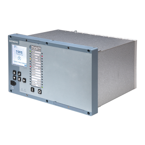
Reyrolle 5 (7SR5) devices are supplied in size 6 and size 12 cases. [sc_7SR5_size6_FrontPhotoAngle, 1, --_--] Figure 1-1 Size 6 Device The devices can be panel mounted or fitted into standard 19 inch rack systems. Dimensions are shown in Figure 2-1 Figure 2-2. Reyrolle 7SR5, Hardware, Manual C53000-T7040-C013-1, Edition 11.2019... - Page 13 Figure 1-2 CAUTION Inserting the Device Element When inserting the device element into the case, handle only from the front of the device fascia and ² ensure no objects obstruct insertion of the element. Reyrolle 7SR5, Hardware, Manual C53000-T7040-C013-1, Edition 11.2019...
- Page 14 Introduction 1.1 Design and Hardware Characteristics [sc_7SR5_Size6_rear, 1, --_--] Size 6 Device (Rear) Reyrolle 7SR5, Hardware, Manual C53000-T7040-C013-1, Edition 11.2019...
- Page 15 Introduction 1.1 Design and Hardware Characteristics [7SR5 Fascia - Example Mimic Displays, 1, --_--] Figure 1-3 Example Mimic Display Reyrolle 7SR5, Hardware, Manual C53000-T7040-C013-1, Edition 11.2019...
- Page 16 Reyrolle 7SR5, Hardware, Manual C53000-T7040-C013-1, Edition 11.2019...
-
Page 17: Devices And Front Fascia Panels
Devices and Front Fascia Panels Dimension Drawings Reyrolle 7SR5, Hardware, Manual C53000-T7040-C013-1, Edition 11.2019... -
Page 18: Dimension Drawings
Devices and Front Fascia Panels 2.1 Dimension Drawings Dimension Drawings [dw_7SR5_E6_dimensions, 1, en_US] Figure 2-1 Size 6 Case Reyrolle 7SR5, Hardware, Manual C53000-T7040-C013-1, Edition 11.2019... - Page 19 Devices and Front Fascia Panels 2.1 Dimension Drawings [dw_7SR5_E12_dimensions, 1, en_US] Figure 2-2 Size 12 Case Reyrolle 7SR5, Hardware, Manual C53000-T7040-C013-1, Edition 11.2019...
- Page 20 Reyrolle 7SR5, Hardware, Manual C53000-T7040-C013-1, Edition 11.2019...
-
Page 21: Device Modules
All devices include the front fascia HMI, a processor module, CT module, and a power supply module. Addi- tional modules are added dependent on the device functionality. Processor Module Power‑Supply Module Binary Input/Binary Output Modules CT Module VT Module Reyrolle 7SR5, Hardware, Manual C53000-T7040-C013-1, Edition 11.2019... -
Page 22: Processor Module
3.1 Processor Module Processor Module Table 3-1 Data Communications Ports Serial port RS485 2 Electrical ethernet ports (optional) RJ45 (Channel 1) RJ45 (Channel 2) 2 Optical ethernet ports (optional) LC (Channel 1) LC (Channel 2) Reyrolle 7SR5, Hardware, Manual C53000-T7040-C013-1, Edition 11.2019... -
Page 23: Power-Supply Module
The case earth stud should be solidly earthed to the panel earth. Terminal B28 (power supply unit) should be connected to the case earth stud. A minimum wire size of 2.5 mm is recommended. Reyrolle 7SR5, Hardware, Manual C53000-T7040-C013-1, Edition 11.2019... -
Page 24: Binary Input/Binary Output Modules
5 Binary inputs Independent circuits, segregated Selectable operate voltage levels: • Range 1: DC 24 V • Range 2: DC 110 V • Range 3: DC 220 V 2 Binary outputs Make contacts Independent circuits/terminals Reyrolle 7SR5, Hardware, Manual C53000-T7040-C013-1, Edition 11.2019... -
Page 25: Ct Module
1 A/5 A user selectable 3 Binary inputs Independent circuits, segregated Selectable operate voltage levels: • Range 1: DC 24 V • Range 2: DC 110 V • Range 3: DC 220 V Reyrolle 7SR5, Hardware, Manual C53000-T7040-C013-1, Edition 11.2019... -
Page 26: Vt Module
1 Binary input Independent circuits, segregated Selectable operate voltage levels: • Range 1: DC 24 V • Range 2: DC 110 V • Range 3: DC 220 V 2 Binary outputs Make contacts Independent circuits/terminals Reyrolle 7SR5, Hardware, Manual C53000-T7040-C013-1, Edition 11.2019... -
Page 27: Working With The Device
Working with the Device Safety Information Reyrolle 7SR5, Hardware, Manual C53000-T7040-C013-1, Edition 11.2019... -
Page 28: Safety Information
Siemens. Problem-free and safe operation of the product depends on the following: • Proper transport • Proper storage, setup and installation • Proper operation and maintenance Reyrolle 7SR5, Hardware, Manual C53000-T7040-C013-1, Edition 11.2019... - Page 29 Operation of equipment with exposed current-transformer circuits is prohibited. Before disconnecting the equipment, ensure that the current-transformer circuits are short-circuited. • The limiting values stated in the document must not be exceeded. This must also be considered during testing and commissioning. Reyrolle 7SR5, Hardware, Manual C53000-T7040-C013-1, Edition 11.2019...
- Page 30 Reyrolle 7SR5, Hardware, Manual C53000-T7040-C013-1, Edition 11.2019...
-
Page 31: Technical Data
Binary Outputs Communication Interfaces Electrical Tests Mechanical Tests Environmental Conditions Operating Conditions 5.10 Reference Conditions and Influencing Variables 5.11 Approvals and Certification 5.12 Design Data 5.13 Assembly Dimensions 5.14 Labeling 5.15 Display Resolution Reyrolle 7SR5, Hardware, Manual C53000-T7040-C013-1, Edition 11.2019... -
Page 32: Analog Inputs
Further technical data for the current and voltage transformers can be found in the Device Manual > Technical Data chapter. NOTE Further information on the measuring accuracy of the analog inputs can be found in the Device Manual > Technical Data chapter. Reyrolle 7SR5, Hardware, Manual C53000-T7040-C013-1, Edition 11.2019... -
Page 33: Supply Voltage
Energizing Voltage IEC 60255‑1 Minimum condition Watt IEC Load (Half BI, BO) Watt 12.8 12.4 11.6 11.3 10.8 10.8 10.1 10.2 10.2 Maximum load Watt 15.5 14.9 13.8 13.2 13.2 12.3 12.5 12.5 Reyrolle 7SR5, Hardware, Manual C53000-T7040-C013-1, Edition 11.2019... - Page 34 Backlight (W) LED – red or green (W) Each 0.01 0.01 0.01 0.01 0.01 0.01 0.01 0.01 LED – yellow (W) Each 0.01 0.01 0.01 0.01 0.01 0.01 0.01 0.01 Binary output Each output Reyrolle 7SR5, Hardware, Manual C53000-T7040-C013-1, Edition 11.2019...
-
Page 35: Binary Inputs
For time-critical applications with low-active signals, consider the specified dropoff times. If necessary, provide for active discharge of the binary input (for example, a resistor in parallel to the binary input or using a change-over contact). Reyrolle 7SR5, Hardware, Manual C53000-T7040-C013-1, Edition 11.2019... -
Page 36: Binary Outputs
Breaking capacity DC inductive 30 W at L/R = 40 ms DC resistive 75 W AC resistive 1250 VA Mechanical/electrical endurance Loaded cycles ≥ 10000 Making cycles ≥ 1000 Breaking cycles ≥ 1000 Reyrolle 7SR5, Hardware, Manual C53000-T7040-C013-1, Edition 11.2019... -
Page 37: Communication Interfaces
120Ω, 0.5 W terminating resistor Last relay 120Ω, 0.5 W Connectors Blade crimp Connection – 2 Wire: OV (System Common) Not Connected [dw_connection2wire, 1, en_US] Connection – 1.5 Pair Wire [dw_connection_1.5wire, 1, en_US] Reyrolle 7SR5, Hardware, Manual C53000-T7040-C013-1, Edition 11.2019... - Page 38 LEDs of the RJ45 Terminals – Integrated Ethernet Interface Ethernet Interface (RJ45) Signal Color Operating Status LED 1 ETH_LED1_N Yellow Continuously lit: 100 Mbit/s Not lit: 10 Mbit/s LED 2 ETH_LED0_N Green Flashing: Comms active Continuously lit: No communication Reyrolle 7SR5, Hardware, Manual C53000-T7040-C013-1, Edition 11.2019...
-
Page 39: Electrical Tests
Binary outputs Electrical fast transient/burst Auxiliary PSU 4 kV (peak), 5 ns/50 ns, 5 kHz immunity Measuring inputs IEC 61000‑4‑4 Binary inputs Binary outputs Comms port 2 kV (peak), 5 ns/50 ns, 5 kHz Reyrolle 7SR5, Hardware, Manual C53000-T7040-C013-1, Edition 11.2019... - Page 40 Conducted emission on auxiliary-voltage lines 150 kHz to 30 MHz limit class A CISPR 22 Radiated emission CISPR 11 30 MHz to 1000 MHz limit class A CISPR 22 1 GHz to 6 GHz limit class A Reyrolle 7SR5, Hardware, Manual C53000-T7040-C013-1, Edition 11.2019...
-
Page 41: Mechanical Tests
X-plane – 3.5 mm displace- ment below crossover IEC 60255‑21‑3, frequency (8 to 9 Hz) 1 gn class 1 above. Y-plane – 1.5 mm displace- ment below crossover frequency (8 to 9 Hz) 0.5 gn above. Reyrolle 7SR5, Hardware, Manual C53000-T7040-C013-1, Edition 11.2019... -
Page 42: Environmental Conditions
Damp heat, steady state IEC 60068-2-78 40 °C, 93 % relative humidity, 56 days Damp heat, cyclic IEC 60068-2-30 6 cycles: 25 °C, 97 % relative humidity 40 °C, 93 % relative humidity Reyrolle 7SR5, Hardware, Manual C53000-T7040-C013-1, Edition 11.2019... -
Page 43: Operating Conditions
• Removing or inserting the withdrawable element under live voltage is prohibited. Some components are electrostatically sensitive in the removed state, no special precautions are required when in normal service conditions. Reyrolle 7SR5, Hardware, Manual C53000-T7040-C013-1, Edition 11.2019... -
Page 44: Reference Conditions And Influencing Variables
AC Current (I Nominal or Rated (1 A/5 A) rated AC Voltage (V Nominal or Rated (40 to 160 V) rated Frequency (f Nominal or Rated (50 Hz/60 Hz) rated Ambient temperature (Tamb) 20 °C Reyrolle 7SR5, Hardware, Manual C53000-T7040-C013-1, Edition 11.2019... -
Page 45: Approvals And Certification
This product is CE compliant to relevant EU directives: 2014/35/EU: ‘Low Voltage Directive’ for electrical equipment designed for use within certain voltage limits Council Directive 2014/30/EU: EMC Directive. 2015/863/EU: Restriction of Hazardous Substances Directive (RoHS3) Other Certification ISO 9001 Quality Management Reyrolle 7SR5, Hardware, Manual C53000-T7040-C013-1, Edition 11.2019... -
Page 46: Design Data
Radius = 50 mm (minimum bending radius) NOTE The length of the cable protection sleeve also to be included in calculations. Tightening Torques for Terminal Screws Fascia lever handles – captive screw 0.3 Nm Reyrolle 7SR5, Hardware, Manual C53000-T7040-C013-1, Edition 11.2019... -
Page 47: Assembly Dimensions
Technical Data 5.13 Assembly Dimensions 5.13 Assembly Dimensions [dw_7SR5_E6_dimensions, 1, en_US] Figure 5-1 7SR5 Size 6 Dimensions Reyrolle 7SR5, Hardware, Manual C53000-T7040-C013-1, Edition 11.2019... - Page 48 Technical Data 5.13 Assembly Dimensions [dw_7SR5_E12_dimensions, 1, en_US] Figure 5-2 7SR5 Size 12 Dimensions Reyrolle 7SR5, Hardware, Manual C53000-T7040-C013-1, Edition 11.2019...
-
Page 49: Labeling
This will direct the user to more meaningful informa- tion. AC 2 kV insulation test of the voltage inputs, current inputs, and binary outputs 5 kV impulse voltage test (type test) in compliance with Class III European CE marking Reyrolle 7SR5, Hardware, Manual C53000-T7040-C013-1, Edition 11.2019... - Page 50 5.14 Labeling Electrical Hazard Refer to device documentation (Product information, Device manual, Hardware manual, Operating manual, and Commu- nication protocol manuals) Waste Electrical and Electronic Equipment Directive (WEEE) Guideline for the Eurasian Market Reyrolle 7SR5, Hardware, Manual C53000-T7040-C013-1, Edition 11.2019...
-
Page 51: Display Resolution
Technical Data 5.15 Display Resolution 5.15 Display Resolution LCD graphic display (Liquid Crystal Display) 128 x 128 pixels Reyrolle 7SR5, Hardware, Manual C53000-T7040-C013-1, Edition 11.2019... - Page 52 Reyrolle 7SR5, Hardware, Manual C53000-T7040-C013-1, Edition 11.2019...
Need help?
Do you have a question about the Reyrolle 7SR5 and is the answer not in the manual?
Questions and answers