Dinstar DAG2500-48S User Manual
Fxs gateway
Hide thumbs
Also See for DAG2500-48S:
- Quick installation manual (14 pages) ,
- Quick installation manual (8 pages) ,
- Quick installation manual (10 pages)
Table of Contents
Advertisement
Quick Links
DAG2500-48S/72S/96S FXS Gateway
User Manual V1.0
Shenzhen Dinstar Co., Ltd.
Address: Floor 18, Building 7A, Vanke Cloud City Phase 1, Xingke 1st Street, Xili Sub-district,
Nanshan District, Shenzhen.
Postal Code: 518052
Telephone: +86 755 61919966
Fax: +86 755 2645 6659
Email:sales@dinstar.com
Website: www.dinstar.com
Advertisement
Table of Contents

Related Manuals for Dinstar DAG2500-48S


Summary of Contents for Dinstar DAG2500-48S
- Page 1 DAG2500-48S/72S/96S FXS Gateway User Manual V1.0 Shenzhen Dinstar Co., Ltd. Address: Floor 18, Building 7A, Vanke Cloud City Phase 1, Xingke 1st Street, Xili Sub-district, Nanshan District, Shenzhen. Postal Code: 518052 Telephone: +86 755 61919966 Fax: +86 755 2645 6659 Email:sales@dinstar.com...
- Page 2 Preface Welcome Thanks for choosing the Dinstar’s Product! We hope you will make full use of this rich-feature FXS Gateway. Contact us if you need any technical support: +86-755-61919966. About This Manual This manual provides information about the introduction of the analog telephone adapter, and about how to install, configure or use it.
-
Page 3: Table Of Contents
Contents Contents 1 Product Introduction ........................ 1 1.1 Overview ................................ 1 1.2 Application Scenario ..........................2 1.3 Outlooks of Products ..........................2 1.3.1 Outlooks of Device (take DAG2500-96S for example) ............. 2 1.3.2 Ports and Connectors ........................3 1.4 Features & Functions ..........................5 1.4.1 Key Features ............................ - Page 4 Contents 3.3 Call Waiting ..............................12 3.4 Call Transfer ..............................13 3.4.1 Blind Transfer ............................ 13 3.4.2 Attended Transfer ..........................13 3.5 Function of Flash-hook ..........................14 3.6 Description of Feature Code ........................14 3.7 Send or Receive Fax ..........................16 3.7.1 Fax Mode Supported ........................
- Page 5 Contents 4.5.2 VLAN (Virtual Local Area Network) ..................... 31 4.5.3 DHCP Option ............................. 34 4.5.4 QoS ..............................35 4.5.5 ARP ..............................35 4.6 SIP Server ..............................36 4.7 IP Profile............................... 39 4.8 Tel Profile ..............................39 4.9 Port ................................39 4.10 Advanced ..............................
- Page 6 Contents 4.12.2 Tel → IP/Tel Caller .......................... 78 4.12.3 Tel → IP/Tel Callee .......................... 80 4.13 Management ............................82 4.13.1 TR069 ..............................82 4.13.2 SNMP ..............................83 4.13.3 Syslog ..............................87 4.13.4 Provision ............................88 4.13.5 Cloud server ............................ 89 4.13.6 User Manage ...........................
- Page 7 Contents 4.15.7 Network Capture .......................... 103 4.15.8 Factory Reset ..........................106 4.15.9 Device Restart ..........................106 5 Glossary ............................. 107...
-
Page 8: Product Introduction
The FXS analog gateway available in the following configurations: ✓ DAG2500-48S, 48 ports FXS gateway ✓ DAG2500-72S, 72 ports FXS gateway ✓ DAG2500-96S, 96 ports FXS gateway... -
Page 9: Application Scenario
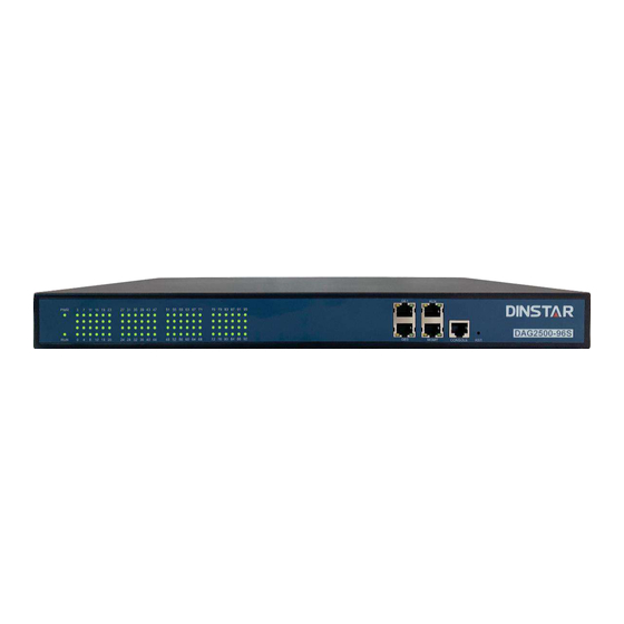
1 Product Introduction 1.2 Application Scenario The application scenario of device is shown as follow: Figure-Application Scenario of the device 1.3 Outlooks of Products Outlooks of Device (take DAG2500-96S for example) 1.3.1 Front View: Back View-Type 1:... -
Page 10: Ports And Connectors
1 Product Introduction Back View-Type 2: Notes: DAG2500-48S/72S/96S has a similar outlook except for the different number of ports. And the AUX port on the front panel means the reserved interface. 1.3.2 Ports and Connectors... - Page 11 1 Product Introduction The description of indicators: Indicator Definition Status Description The gateway is powered on Power Indicator The gateway is powered off or there is no power supply Slow The gateway is running properly Flashing (Slow Flashing means the running indicator flashing for 2 seconds) Fast SIP account is registered...
-
Page 12: Features & Functions
Fully compatible with leading IMS/NGN, SIP based IP telephony system ⚫ 1.4.2 Physical Interfaces Phone Connector ⚫ DAG2500-48S: 48 FXS, RJ 45 or RJ21, 50 PIN DAG2500-72S: 72 FXS, RJ 45 or RJ21, 50 PIN DAG2500-96S: 96 FXS, RJ 45 or RJ21, 50 PIN Console: ⚫ 1* RS232, 115200bps Network Interfaces: ⚫... -
Page 13: Voice Capabilities & Fax
1 Product Introduction 1.4.3 Voice Capabilities & Fax Recording ⚫ T.38/Pass-through ⚫ Modem/POS ⚫ Silence Suppression ⚫ Bandwidth Optimization ⚫ Comfort Noise Generation (CNG) ⚫ Voice Activity Detection (VAD) ⚫ Packet Loss Concealment ⚫ Adaptive (Dynamic) Jitter Buffer ⚫ Programmable Gain Control ⚫... -
Page 14: Call Features
1 Product Introduction IPv4 and IPv6 ⚫ Outbound Proxy ⚫ Master/Slave Server ⚫ RFC2806 TEL URI ⚫ RFC3581 NAT, rport ⚫ VLAN 802.1P/802.1Q ⚫ RFC4028 Session Timer ⚫ DNS SRV/A Query/NATPR Query ⚫ NAT: STUN, Static/Dynamic NAT ⚫ 1.4.6 Call Features Digit map ⚫... -
Page 15: Security
Operating Temperature: 0℃ ~ 45℃ ⚫ Storage Temperature: -20℃ ~80℃ ⚫ Humidity: 10%-90% Non-Condensing ⚫ Dimensions(W/D/H): 440*328*44mm (1U) ⚫ Unit Weight: ⚫ DAG2500-48S: 4.1kg DAG2500-72S: 4.25kg DAG2500-96S: 4.4kg Compliance: CE and FCC ⚫ 1.4.9 Maintenance ⚫ Ping/Tracert Test ⚫ Network Capture ⚫... - Page 16 1 Product Introduction SNMP, TR069, Provision ⚫ NTP/Daylight Saving Time ⚫ IVR local Maintenance ⚫ RADUIS Authentication Management ⚫ Cloud-based Management (NMS) ⚫ Syslog: Debug, Info, Error, Warning, Notice ⚫ Configuration Backup/Restore ⚫ Firmware Upgrade via HTTP/HTTPS/TFTP/FTP/HTTP ⚫...
-
Page 17: Quick Installation
2 Quick Installation Quick Installation 2.1 Installation Attentions To avoid unexpected accident or device damage, please read the following instructions before installing the device: The device is equipped with both RJ45 and RJ21 ports; ⚫ Anti-jamming: to reduce the interference with telephone calls, it’s highly ⚫... -
Page 18: Installation Steps
2 Quick Installation 2.2 Installation Steps Connection Diagram for DAG2500-48S/72S/96S ⚫ Connect gateway with network via a switch ⚫ Connect FXS ports with analog phones, connect gateway with power input ⚫ and grounding lug... -
Page 19: Basic Operation
3 Basic Operation Basic Operation 3.1 Methods to Number Dialing There are two methods to dial telephone number or extension number: Dial the called number and wait for 4 seconds for dialing timeout, or dial the ⚫ called number directly (the system will judge whether the dialing is completed according to Digitmap and Regular Expression dial plans). -
Page 20: Call Transfer
3 Basic Operation 3.4 Call Transfer 3.4.1 Blind Transfer Blind transfer is a call transfer in which the transferring party connects the call to a third party without notifying the third party. Example: A gives a call to B and B wants to blindly transfer the call to C. Operation instructions are as follows: 1. -
Page 21: Function Of Flash-Hook
3 Basic Operation 3. B presses the flash button (or flash hook), and then dials the extension number of C (end up with #). Then one of the following situations will happen: If C answers the call and accepts the transfer, B will hand up the phone, and then C and A go into conversation. - Page 22 3 Basic Operation Dial *152* to set IPv4 address, for example: *152* Dial *152*192*168*1*10# to set IPv4 address as 192.168.1.10 Dial *153* to set IPv4 netmask, for example: *153* Dial *153*255*255*0*0*# to set IPv4 netmask as 255.255.0.0 Dial *156* to set IPv4 gateway, for example: *156* Dial *156*192*168*1*1# to set IPv4 gateway as 192.168.1.1 *170#...
-
Page 23: Send Or Receive Fax
3 Basic Operation *79# Disable the ‘No Disturbing’ service *200# Dial *200# to access voicemail Dial *# in 2 seconds to hold the call (back the call by ""hook flash" or dial *#) Dial *# to release the current call and restore inactive call Note: A voice prompt indicating successful configuration will be played after each configuration procedure. -
Page 24: Function Of Rst Button
3 Basic Operation 3.8 Function of RST Button Press the RST button of the device for a moment, the running indicator will turn from “slow flashing” into “no flashing”, and then turn into “slow flashing” again. That means the device has been restored back to factory setting. 3.9 Query IP Address and Restore Default Setting Query IP Address: After connecting a telephone to the FXS port, you can dial *158# to query the... -
Page 25: Configurations On Web Interface
4 Configurations on Web Interface Configurations on Web Interface 4.1 Access WEB Interface First, users connect the device to the network and refer to the network topology 3 Basic Operation diagram for connection. Then refer to the chapter and dial *158# to query the IP address of the device. - Page 26 4 Configurations on Web Interface On the PC, click 'Network (or Ethernet) →Properties'. Double-click ‘Internet Protocol Version 4 (TCP/IPv4)'. Select 'Use the following IP address', and then enter an available IP address ‘192.168.11.XXX' which is at the same network segment with '192.168.11.1'.
-
Page 27: Log In Web
4 Configurations on Web Interface Then, check the connectivity between the PC and the device. Click Start → Run of PC and enter cmd to execute ‘ping 192.168.11.1’ to make sure the IP address is pingable. 4.1.2 Log in WEB Open a web browser and enter the IP address (the default IP is 192.168.11.1). -
Page 28: Navigation Tree
4 Configurations on Web Interface 4.2 Navigation Tree The web management system of the device consists of the navigation tree and configuration interfaces with more details. Choose a node of the navigation tree to enter a configuration interface. Figure-Navigation Tree of Web Interface 4.3 Status &... -
Page 29: System Information
4 Configurations on Web Interface 4.3.1 System Information Log in the Web interface, and then click Status & Statistics → System Information, and the following page will be displayed. On the page, you can view the information of device ID, MAC address, IP addresses, version information, server register status and so on. - Page 30 4 Configurations on Web Interface There are three kinds of IP address for the WAN port and LAN port: DHCP: Obtain IP address automatically. The gateway is regarded as a DHCP client, which sends a broadcast request and looks for a DHCP server from the LAN to answer.
- Page 31 4 Configurations on Web Interface Password: the password of PPPoE ⚫ Server Name: the name of the server where ⚫ PPPoE is placed IP addresses of primary DNS server and standby DNS Server DNS server are displayed. Cloud Register Status Whether the device is registered to cloud or not.
-
Page 32: Dtu Status
4 Configurations on Web Interface 4.3.2 DTU Status The following figures on Status & Statistics → DTU Status page shows the DTU card information and DTU channel information, and users can view the connection status of DTU through this page. 4.3.3 Port Status On the Status &... -
Page 33: Current Call
4 Configurations on Web Interface Figure-Registration Status of Each FXS Port or Port Group SIP User status: Registered: the port or port group is registered to SIP server successfully; Unregistered: the port or port group fails to be registered to SIP server. Current Call 4.3.4 On the Status &... -
Page 34: Rtp Session
4 Configurations on Web Interface 4.3.5 RTP Session On the Status & Statistics → RTP Session page, users can view the real-time RTP session information, including: port, source, destination, payload type, packet period, local port, peer IP, peer port, sent packets, received packets, lost packets rate, jitter, and duration. -
Page 35: Record Statistics
4 Configurations on Web Interface Parameter Explanation whether CDR is enabled; check Yes, the CDRs will be Enable CDR displayed after the call; or the CDRs will not be displayed after the call ends Port Select one port or all ports to filter CDRs Filter CDRs according to the call state, users can select Call State All, Not Answer, Complete and Fail... -
Page 36: Quick Setup Wizard
4 Configurations on Web Interface Figure-Record Statistics 4.4 Quick Setup Wizard Quick setup wizard guides user to configure the device step by step. User only needs to configure network, SIP server and SIP port in the Quick Setup Wizard interface. Basically, after these three steps, users can make voice call via the device. - Page 37 4 Configurations on Web Interface Figure-Local Network Setting...
-
Page 38: Vlan (Virtual Local Area Network)
4 Configurations on Web Interface Parameter Explanation There are 2 IP protocols the device IP Protocol supported, IPv4 or IPv6 The working mode for GE0/GE1. It WAN Dual Mode supports separation, bonding, and bridge The device obtains IP address through Obtain an IP address automatically DHCP server Use the following IP address... - Page 39 4 Configurations on Web Interface Figure-Configure VLAN Table-Explanation of VLAN Parameters Parameter Explanation VLAN1/VLAN2/VLAN3 The device supports three VLANs at most. Please enable VLAN according to actual needs. Data/Voice/Management Select what kind of messages are allowed to go through this VLAN. For example, if the checkbox on the left of data is selected, it means data messages are subject to the following network setting of this VLAN.
- Page 40 4 Configurations on Web Interface VLAN ID(1-4094) Set an ID to identify a VLAN based on 802.1Q protocol. Range is from 1 to 4094. Priority(0-7) Set the priority of a VLAN based on 802.1P protocol. 0 is the highest priority. Obtain an IP address The device obtains IP address through DHCP server automatically...
-
Page 41: Dhcp Option
4 Configurations on Web Interface DHCP Option 4.5.3 When the device works as a DHCP client and applies for an IP address, DHCP server will return packets which include an IP address as well as configuration information of enabled option fields. The following is the meaning of the option fields involved in the device (that means the following option fields are enabled, DHCP server will return information of corresponding option fields:... -
Page 42: Qos
4 Configurations on Web Interface 4.5.4 The device can label QoS priority on the IP messages it sends out, so as to resolve network delay or network congestion. Meanwhile, the device can give different QoS tags for management-related packets of Web/Telnet, voice packets and signal packets. -
Page 43: Sip Server
4 Configurations on Web Interface 4.6 SIP Server SIP server is the main component of SIP/IP network and is responsible for establishing all SIP calls. SIP server is also called SIP proxy server or register server. Both IPPBX and softswitch can act as the role of SIP server. Figure-Configure SIP Server Information... - Page 44 4 Configurations on Web Interface Table-Parameter Explanation of SIP Server Parameter Explanation SIP Server The IP address or domain name of the SIP server. It is provided by service provider or system admin. SIP Server Port The service port of the SIP server. It is 5060 by default.
- Page 45 4 Configurations on Web Interface Registration Limit The number of registrations per second (0 means unlimited) (counts/time, time: 0 means unlimited) Send SIP All SIP accounts are logged out and then re- registered after the device is rebooted Unregistration Request when the Device Restart The MOH (Music on Hold) feature provides music...
-
Page 46: Ip Profile
4 Configurations on Web Interface 4.7 IP Profile IP profile is mainly consisting of a series of IP related parameters include SIP server, outbound proxy, DTMF, codecs etc. which are used to configure different parameters for each FXS port. 4.8 Tel Profile Tel profile is mainly consisting of a series of line related parameters include FAX, gain value etc. - Page 47 4 Configurations on Web Interface Figure-Configure SIP Account for Port Registration...
- Page 48 4 Configurations on Web Interface Table-Explanation of Parameters Related to SIP Registration Parameter Explanation Port The FXS port corresponding to this account Disable port Whether to disable port temporally Registration Whether to enable registration for the port IP Profile Assign IP profile (which need to be created in advance) Tel Profile Assign Tel profile (which need to be created in advance) Display name...
- Page 49 4 Configurations on Web Interface Caller ID Enable or disable caller ID for corresponding port. If it is disabled, the caller ID for the calls through the port won’t be displayed. Number for CFU Call forward unconditional. All incoming calls will be forwarded to pre-assigned number automatically Number for CFB Call forward on busy.
-
Page 50: Advanced
4 Configurations on Web Interface 4.10 Advanced 4.10.1 Line Parameter On the Advanced→ line page, you can configure FXS parameters which include for call progress tone, auto gain control, fax parameters and so on. - Page 51 4 Configurations on Web Interface Parameter Explanation Call Process Tone The signal tone standard after a phone is picked up. Choose national standards from the drop- down box. Default value is USA. Call Waiting Tone Set the duration, gap and repeat count of call waiting tone Auto Gain Control Whether to enable automatic gain control...
- Page 52 4 Configurations on Web Interface Include “a=fax” If this parameter is enabled, “a=fax” attribute will be carried in SDP Attribute Include “a=X- If this parameter is enabled, “a=X-modem” attribute will be carried in SDP modem” Attribute Include “a=modem” If this parameter is enabled, “a=modem” attribute will be carried in SDP Attribute If this parameter is enabled, “...
-
Page 53: Fxs Parameter
4 Configurations on Web Interface 4.10.2 FXS Parameter On the Advanced→ FXS/page, you can configure FXS parameters which include send polarity reversal, detect hook flash, CID type and so on. Figure-Configure FXS Parameters... - Page 54 4 Configurations on Web Interface Table-Explanation of FXS Parameters Parameter Explanation Send Polarity Reversal If polarity reversal is enabled, call tolls will be calculated based on the changes in voltage. If polarity reverse is disabled, you need to set the time for offhook detection and call tolls will be calculated starting from the set time.
- Page 55 4 Configurations on Web Interface Delay of sending CID after The time how long the caller ID will be delayed when the caller ID is set to be Ringing displayed after ringing. Default value is 500ms. Caller Number Preferred Users can configure the primary caller number that will be called out to the target when FXS Call Out number in priority.
-
Page 56: Media Parameter
4 Configurations on Web Interface 4.10.3 Media Parameter Media parameters mainly include RTP start port, DTMF parameter, preferred Vocoder, etc. Figure-Configure Media Parameters Table-Explanation of Media Parameters Parameter Explanation RTP Start Port When ‘Use Random Port’ is not selected, you need to configure a start port for RTP. - Page 57 4 Configurations on Web Interface SRTP Mode Configure whether RTP is encrypted DTMF Method Include SINGAL, INBAND and RFC2833 RFC2833 Payload Type For an incoming call, choose local or remote RFC2833 payload type as the preferred payload type Preferred (Incoming Call) RFC2833 Payload Type Local payload value, default value is 101...
-
Page 58: Service Parameter
4 Configurations on Web Interface Service Parameter 4.10.4 Service parameters include timeout for dialing, digitmap, MWI message and so... - Page 59 4 Configurations on Web Interface Parameter Explanation Timeout for off-hook Mainly used to define a timer that when the user is off hook an analog phone without dial any digits Timeout for dialing With the help of dialing timeout, you can limit the time between two digits while users are typing the digits of a number through an extension.
- Page 60 4 Configurations on Web Interface IP-to-IP Call If this parameter is enabled, user can dial IP address through a phone to call destination gateway. Only Accept Call from If this parameter is enabled, the device only accepts incoming call from SIP server only. Default value is ACL (SIP server or IP ‘not enable’.
-
Page 61: Sip Compatibility
4 Configurations on Web Interface Configure the domain name re-resolution interval. Domain Re-resolution The range is 0-3600, and 0 means no refresh Interval(0-3600,0:No Refresh) Configure echo cancellation duration Echo Cancel Tail Digitmap is used for number dialing of calls through FXS ports of the device. Parameter Explanation Supported Objects... - Page 62 4 Configurations on Web Interface Figure-Configure SIP Parameters...
- Page 63 4 Configurations on Web Interface Table-Explanation of SIP Parameters Parameter Explanation Whether to enable RFC3407 support. If this RFC3407 Support parameter is enabled, the device will support RFC3407 which defines the SDP capability of backward compatibility. When disabled, the "user=phone" is not carried Forbid "user=phone"...
- Page 64 4 Configurations on Web Interface Send New REGISTER when If this parameter is enabled, the value of Recv 423 Response ‘expires’ header will be automatically updated and REGISTER will be re-sent after receiving of 423 response. Verify the Contact Header Enabled it, the contact header will be verified, in REGISTER Response if the verification failed, the registration will...
- Page 65 4 Configurations on Web Interface 18x Response It supports 18x Response with SDP, Last 18x Preferred(Without Response, and Local Ring Tone Only. Effective P-Early-Media) Flashhook Operation Mode Choose Mode one, Mode two or Mode three Attended Transfer Trigger Choose ‘Onhook’ or ‘Flashhook +4’ Multipart Payload Support Support MIME types.
- Page 66 4 Configurations on Web Interface Min-SE The minimum interval for refreshing session; default value is 1800s. The Min-SE header field indicates the minimum value for the session interval. Session Refresh Method The method to refresh session; default value is INVITE. Value of T1 timer in SIP protocol, default is 500ms Value of T2 timer in SIP protocol, default is...
-
Page 67: Nat Parameter
4 Configurations on Web Interface NAT Parameter 4.10.6 NAT Traversal (Network Address Translator Traversal) is a computer networking technique of establishing and maintaining Internet protocol connections across gateways that implement network address translation (NAT). NAT breaks the principle of end-to-end connectivity originally envisioned in the design of the Internet. -
Page 68: Speed Dial
4 Configurations on Web Interface Via of Message Via header in SIP messages uses local network address or NAT address Contact of Message Contact header in SIP messages uses local network address or NAT address SDP of Message SDP in SIP messages uses local network address or NAT address 4.10.7 Speed Dial... -
Page 69: Feature Code
4 Configurations on Web Interface Feature Code 4.10.8... - Page 70 4 Configurations on Web Interface Parameter Explanation Inquiry LAN IP Dial*158# to obtain device’s LAN port IP address Inquiry Phone Number Dial*114# to obtain port account Inquiry Port Group Number Dial *115# to obtain port group number Inquiry Registration Status Dial *168# to query the register status of a FXS port Remove Login Limit...
-
Page 71: System Parameter
4 Configurations on Web Interface Call Waiting Deactivate *50#, forbid call waiting function Blind Transfer If the call transfer to 801, first hook flash and then dial the * 87 * 801# Call Forward Unconditional *72*+ phone number#, transfer the call from the phone number Activate Call Forward Unconditional... - Page 72 4 Configurations on Web Interface Figure-Configure System Parameters...
- Page 73 The service port of secondary NTP server; Default port is 123 port SYN Interval The interval to synchronize the time of the DAG2500-48S/72S/96S. Default value is 3600s. Time Zone The time zone of the device; Default configuration is United States central time, Chicago. Daylight Saving Time...
-
Page 74: Call & Routing
4 Configurations on Web Interface 4.11 Call & Routing 4.11.1 Wildcard Group 4.11.2 Port Group When two or more FXS ports need to register with a same SIP account, you can group the ports together and then set an account for the group on the Call & Routing →... - Page 75 4 Configurations on Web Interface Figure-Add Port Group...
- Page 76 4 Configurations on Web Interface Table-Parameter Explanation of Port Group Parameter Explanation Index The NO. of the port group; It uniquely identifies a route. Registration Registration IP Profile IP Profile Description The description of the port group; it is used to identify the port group.
- Page 77 4 Configurations on Web Interface Offhook Auto-Dial An extension or phone number is pre-assigned here so that the number is automatically dialed as soon as user picks up the phone Auto-dial Delay time How long auto-dialing will be delayed Port Select It specifies the policy for selecting a port for ringing in the port group ...
-
Page 78: Ip Trunk
4 Configurations on Web Interface 4.11.3 IP Trunk A peer-to-peer VoIP call occurs when two VoIP phones communicate directly over IP network without IP PBXs between them. IP trunk helps establish peer- to-peer call between gateway and VoIP phones. IP trunk will be used in routing configuration. -
Page 79: Routing Parameter
4 Configurations on Web Interface 4.11.4 Routing Parameter Routing parameter determines a call routed before or after manipulation. Figure-Configure Routing Parameter Table-Explanation of Routing Parameters Parameter Explanation Calls from IP Choose calls from IP network are routed before manipulation or after manipulation. Calls from Choose calls from analog lines are routed before manipulation or after manipulation. - Page 80 4 Configurations on Web Interface Table-Parameter Explanation of IP →Tel Routes Parameter Explanation Index Index of the IP →Tel routing; range is from 0 to127; 0 is the highest priority. Description Description of the IP →Tel routing; it is used to identify the IP →...
-
Page 81: Tel → Ip/Tel Routing
4 Configurations on Web Interface 4.11.6 Tel → IP/Tel Routing Calls from the FXS port or port group can be routed to IP trunk or ports of SIP server/other device through Tel →IP/Tel routing. Figure-Add Tel →IP/Tel Route... -
Page 82: Manipulation
4 Configurations on Web Interface Table-Explanation of Tel →IP/Tel Route Parameter Explanation Index The index of this Tel →IP/Tel routing; range is from 0 to 127. Each index cannot be used repeatedly. Routing priority: 0 is the highest priority. Description The description of this Tel →IP/Tel routing;... -
Page 83: Ip → Tel Called
4 Configurations on Web Interface IP → Tel Called 4.12.1 On the IP → Tel Called submenu page, you can set rules for manipulating the called number of IP → Tel calls. Figure-Add IP →Tel Called Number Manipulation... - Page 84 4 Configurations on Web Interface Table-Explanation of Parameters for IP →Tel Called Number Manipulation Parameter Explanation Index The index of this manipulation; range is from 0 to 127. Each index cannot be used repeatedly. 0 is the highest priority Description Description of this manipulation;...
-
Page 85: Tel → Ip/Tel Caller
4 Configurations on Web Interface Tel → IP/Tel Caller 4.12.2 On the Tel → IP/Tel Caller page, you can set rules for manipulating the caller number of Tel → IP/Tel calls. Figure-Add Tel → IP/Tel Caller Number Manipulation... - Page 86 4 Configurations on Web Interface Table-Explanation of Parameters for IP →Tel Called Number Manipulation Parameter Explanation Index The index of this manipulation; range is from 0 to 127. Each index cannot be used repeatedly. 0 is the highest priority Description Description of this manipulation;...
-
Page 87: Tel → Ip/Tel Callee
4 Configurations on Web Interface 4.12.3 Tel → IP/Tel Callee On the Tel → IP/Tel Callee page, you can set rules for manipulating the called number of Tel → IP/Tel calls. Figure 4-1 Add Tel → IP/Tel Callee Number Manipulation... - Page 88 4 Configurations on Web Interface Table-Explanation of Parameters for Tel → IP/Tel Callee Number Manipulation Parameter Explanation Index The index of this manipulation; range is from 0 to 127. Each index cannot be used repeatedly. 0 is the highest priority Description Description of this manipulation;...
-
Page 89: Management
4 Configurations on Web Interface Number of Digits to Leave For an incoming call, reserved digits from callee number, starting count numbers from from Right right of callee number. 4.13 Management 4.13.1 TR069 TR069 is short for Technical Report 069, which provides a commonly-used framework and protocol for next-generation network devices. -
Page 90: Snmp
4 Configurations on Web Interface Table-Explanation of TR069 Parameters Parameter Explanation TR069 Choose whether to enable TR069; it is ‘not enable’ by default. ACS URL The IP address or domain name of ACS, which is provided by service provider. Username(ACS) Username of ACS, which is provided by service provider. - Page 91 4 Configurations on Web Interface SNMP is widely used in network management for network monitoring. SNMP exposes management data in the form of variables on the managed systems organized in a management information base which describe the system status and configuration. These variables can then be remotely queried (and, in some circumstances, manipulated) by managing applications.
- Page 92 4 Configurations on Web Interface Table-Explanation of SNMP Parameters Parameter Explanation SNMP The device supports three versions of SNMP, namelyV1、V2C and V3. Community Community configuration exists in V1 and V2C. Configuration Community: fill in a community name used to read through SNMP protocol;...
- Page 93 4 Configurations on Web Interface Access Configuration Access configuration exists in V1, V2C and V3, under which permission of read, write or notify is configured for a community group. Group: choose a group name that has been configured. Read: Choose a ‘read’ view for the group. Write: Choose a ‘write’...
-
Page 94: Syslog
4 Configurations on Web Interface 4.13.3 Syslog Syslog is a standard for message logging. It allows separation of the software that generates messages, the system that stores messages, and the software that reports and analyzes messages. It also provides a means to notify administrators of problems or performance. -
Page 95: Provision
4 Configurations on Web Interface 4.13.4 Provision Provision is used to make the device automatically upgrade with the latest firmware stored on an http server, a ftp server or a tftp server. Please refer to the Instruction for Using Provision. Figure-Provision Table-Explanation of Provision Parameters Parameter... -
Page 96: Cloud Server
4 Configurations on Web Interface 4.13.5 Cloud server You can register the device to cloud server, and then the device can be managed by the cloud server. Figure-Configure Cloud Server Table-Explanation of Parameters for Cloud Server Parameter Explanation Server Address The IP address of the cloud server Port The listening port of the cloud server... -
Page 97: Remote Server
4 Configurations on Web Interface Table-Explanation of Parameters for adding a User Parameter Explanation Username Username Group Support User and Guest Enabled Enabled Password Password Confirm Password Confirm password 4.13.7 Remote Server In case that you need remote technical support, technical support engineers can connect your device with a service server on the Management →Remote Server page, so as to better help you to solve problems. -
Page 98: Record Parameter
4 Configurations on Web Interface Parameter Explanation Server URL/IP Server URL/IP Server Port Server Port 4.13.8 Record Parameter Parameter Explanation Enable or disable the recording function Set recording server address, and support IP address Server Address or domain name Rcd Port Set the recording server port, the default is 2999 Support setting 3 recording time periods, the Rcd Period Select... -
Page 99: Radius Parameter
4 Configurations on Web Interface Radius Parameter 4.13.9 Parameter Explanation Radius Enable or disable Radius Local Port Port of the local Radius client Device Behavior Upon Support Verify Access Locally and Deny Access. RADIUS Timeout Server IP IP address of the Radius server Server Auth Port Authentication port of Radius server Server Key... -
Page 100: Action Url
4 Configurations on Web Interface 4.13.10 Action URL Action URL is a means of allowing VoIP platform/VoIP server to learn about the statuses of the device. This is realized by GET request over the HTTP protocol. During the transmission of status, some data (such as device ID, mac address, called/caller number, IP address) carried in GET request can also be reported to VoIP platform/VoIP server. -
Page 101: Sip Pnp
4 Configurations on Web Interface SIP PNP 4.13.11 Gateway can restore or upgrade the system firmware by SIP PNP method. The process of SIP PNP is follow: Gateway reproducibly send SIP subscribe requests to broadcast. ⚫ Once, the gateway received Notify message from a server and get a URL. ⚫... -
Page 102: Nms Configuration
4 Configurations on Web Interface 4.13.12 NMS Configuration Network Management System (NMS) is an easy-to-use and centralized tool to manage, monitor and troubleshoot of all the devices including Gateways, IP Phones, IP PBXs, Session Border Controllers, and SIP Intercoms. With device management, alarm system, service management, log management, report management and statistical analysis, it allows enterprises and service providers to centrally and easily deploy and manage a large network of devices. -
Page 103: Telnet Acl
4 Configurations on Web Interface Figure-Add IP Address to Web ACL Parameter Explanation ACL for WEB ACL for WEB Delete IP address Add IP address 4.14.2 Telnet ACL ACL (Access Control List) for Telnet is used to configure IP addresses that are allowed to access the Telnet Interface of the device. -
Page 104: Passwords
4 Configurations on Web Interface Figure-Add IP Address to Telnet ACL Parameter Explanation ACL for TEL ACL for Telnet Delete IP address Add IP address Passwords 4.14.3 You can configure or modify the username and password for logging in the Web interface and the Telnet interface of the device on this page. -
Page 105: Encrypt
4 Configurations on Web Interface Figure-Modify Username and Password 4.14.4 Encrypt When the device is registered to a VOS softswitch, you can encrypt SIP and RTP for the VOS softswitch. Figure-Encrypt SIP and RTP Note: If SIP encryption is enabled, heartbeat and anonymous calls should be disabled. -
Page 106: Tools
4 Configurations on Web Interface 4.15 Tools 4.15.1 Firmware Upload On the Tools → Firmware Upload page, you can upload a new firmware version from a local folder. Figure-Upload Firmware Steps of Firmware Uploading: Step 1. Check the current firmware version on the Status & Statistics →System Information page. -
Page 107: Data Backup
4 Configurations on Web Interface 4.15.2 Data Backup On the Tools → Data Backup page, you can download and backup configuration data, device status and summary messages on local computer. Figure-Backup Data 4.15.3 Data Restore On the Tools → Data Restore page, you can restore configuration data through uploading a data file from local computer. -
Page 108: Outward Test
4 Configurations on Web Interface Outward Test 4.15.4 Outward test enables you to diagnose the physical function of FXS port which follow the GR909 standard. To start outward test, select the FXS ports to be tested and click ‘Start’. The testing may take a few minutes. Figure-Execute Outward Test Test Results: OK: the physical function of the tested FXS ports is working well;... -
Page 109: Ping Test
4 Configurations on Web Interface 4.15.5 Ping Test Ping is used to examine whether a network works as normal through sending test packets and calculating response time. Instructions for using Ping: 1. Enter the IP address or domain name of a network, a website or a device in the input box of Ping, and then click Start. -
Page 110: Network Capture
4 Configurations on Web Interface Figure-Execute Tracert Test Destination: the IP address or domain name of a destination device that needs to be tracked. Max Hops: the maximum hops for searching the above IP address or domain name. For example, if ‘max hops’ is set as 30, and the configured IP address or domain name cannot be reached within 30 hops, it’s thought that the IP address or domain name cannot be searched. - Page 111 4 Configurations on Web Interface Figure-Capture PCM Packages Start’ Click “ to enable PCM capture Dialing out through the device, start talking a short while then hang up the call. Stop’ Click ‘ to disable network capture ...
- Page 112 4 Configurations on Web Interface Click ‘Stop’ to disable syslog capture Save the capture to local computer The capture package is named ‘capture(x).pcap’. x is the serial number of capturing and will be added 1 in next time. DSP Capture: DSP capture helps to analyze voice stream inside DSP chipset.
-
Page 113: Factory Reset
4 Configurations on Web Interface Figure-Customized Capturing 4.15.8 Factory Reset Click ‘Apply’ to restore configurations of the device to the factory default settings. Figure-Reset Device to Factory Default Setting 4.15.9 Device Restart If some parameters are changed, you are required to restart the device for the configurations or changes to take effect. -
Page 114: Glossary
5 Glossary Glossary Abbr. Full Name Address Resolution Protocol Caller Identity Domain Name System Do NOT Disturb DTMF DTMF:Dual Tone Multi Frequency DHCP Dynamic Host Configuration Protocol Demilitarized Zone DDNS Dynamic Domain Name Server Digital Signal Process Network Time Protocol PPPOE Point-to-point Protocol over Ethernet PSTN... - Page 115 5 Glossary SNMP Simple Network Management Protocol Real Time Protocol User Datagram Protocol...
Need help?
Do you have a question about the DAG2500-48S and is the answer not in the manual?
Questions and answers