Table of Contents
Advertisement
Quick Links
AN661
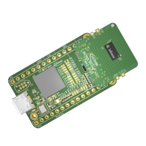
BGT60LTR11AIP EBG shield
XENSIV™ 60 GHz radar system platform
B o a r d v e r s i o n V 3 . 1
About this document
Scope and purpose
This application note describes the function, circuitry, and performance of the 60 GHz radar BGT60LTR11AIP
EBG shield, part of Infineon's XENSIV™ 60 GHz radar system platform. The shield provides the supporting
circuitry to the on-board BGT60LTR11AIP monolithic microwave integrated circuit (MMIC) Infineon's 60 GHz
radar chipset with antenna-in-package (AIP). An electromagnetic band gap (EBG) structure is added to reduce
the impact of the neighboring components on the radar MMIC resulting in a homogeneous field of view (FoV),
which makes the BGT60LTR11AIP the appropriate choice for ceiling-mounted applications. In addition to the
autonomous mode configuration, the shield offers a digital interface for configuration and transfer of the
acquired radar data to a microcontroller board, e.g., Radar Baseboard MCU7.
Intended audience
The intended audiences for this document are design engineers, technicians, and developers of electronic
systems, working with Infineon's XENSIV™ 60 GHz radar sensors.
Related documents
Additional information can be found in the documentation provided with the
Radar Development Kit
tool in the
Infineon Developer Center
(IDC), or from
www.infineon.com/60GHz
Application note
Please read the sections "Important notice" and "Warnings" at the end of this document
Revision 1.00
www.infineon.com
2023-02-14
Advertisement
Table of Contents

Related Manuals for Infineon BGT60LTR11AIP EBG


Summary of Contents for Infineon BGT60LTR11AIP EBG
-
Page 1: About This Document
This application note describes the function, circuitry, and performance of the 60 GHz radar BGT60LTR11AIP EBG shield, part of Infineon’s XENSIV™ 60 GHz radar system platform. The shield provides the supporting circuitry to the on-board BGT60LTR11AIP monolithic microwave integrated circuit (MMIC) Infineon’s 60 GHz radar chipset with antenna-in-package (AIP). -
Page 2: Table Of Contents
BGT60LTR11AIP EBG shield XENSIV™ 60 GHz radar system platform Table of contents Table of contents About this document ........................1 Table of contents ..........................2 Introduction .......................... 3 60 GHz radar system platform ........................ 3 Key features ............................. 4 System specifications ......................5 Hardware description ...................... -
Page 3: Introduction
The BGT60LTR11AIP EBG shield demonstrates the features of the BGT60LTR11AIP MMIC and gives the user a “plug and play” radar solution. The shield can also be attached to an Arduino MKR board or an Infineon Radar Baseboard MCU7. A graphical user interface (GUI) is available via... -
Page 4: Key Features
Introduction Key features The BGT60LTR11AIP EBG shield is optimized for fast prototyping designs and system integrations, as well as initial product feature evaluations. In addition, the sensor can be integrated into systems like laptops, tablets, TVs, speakers, etc. to “wake” them up based on motion (or direction of motion) detection, put them to sleep or auto-lock when no motion is detected for a defined amount of time. -
Page 5: System Specifications
BGT60LTR11AIP EBG shield XENSIV™ 60 GHz radar system platform System specifications System specifications Table 1 gives the specification of the BGT60LTR11AIP EBG shield. Table 1 BGT60LTR11AIP EBG shield specifications Parameter Unit Min. Typ. Max. Comments System performance Detection range –... -
Page 6: Hardware Description
Overview The BGT60LTR11AIP EBG shield is a very small PCB of 20.2 mm x 19.15 mm size. Mounted on top of the PCB is a BGT60LTR11AIP, Infineon’s 60 GHz radar sensor. The PCB can be manufactured using a standard FR4 laminate, as the antennas are integrated into the chip package. -
Page 7: Bgt60Ltr11Aip Mmic
The interrupt request (IRQ) line can be used to trigger the MCU when new data need to be fetched. BGT60LTR11AIP MMIC The BGT60LTR11AIP MMIC (Figure 5) serves as the main element on the BGT60LTR11AIP EBG shield. The MMIC has one transmit antenna and one receive antenna integrated into the package. The package dimensions are 6.7 mm (±0.1 mm) x 3.3 mm (±0.1 mm) x 0.56 mm (±0.05 mm), as illustrated in Figure 6 and Figure 7. - Page 8 BGT60LTR11AIP EBG shield XENSIV™ 60 GHz radar system platform Hardware description The analog baseband (ABB) unit consists of an integrated sample-and-hold (S&H) circuit for low-power duty- cycled operation followed by an externally configurable HPF, a variable-gain amplifier (VGA) stage and a low- pass filter (LPF).
-
Page 9: Sensor Power Supply
MCU7 provides a low-noise power supply. Figure 8 depicts the schematics of the LPFs employed to decouple the supplies of the different power rails in the BGT60LTR11AIP EBG shield. High attenuation of voltage fluctuations in the MHz regime is provided by ferrite beads (L1, L3 and L5). For example, the SPI, which runs up to 50 MHz, induces voltage fluctuations on the digital domain, which would then couple into and interfere with the analog domain without the decoupling filters. -
Page 10: External Capacitors
BGT60LTR11AIP EBG shield XENSIV™ 60 GHz radar system platform Hardware description consume only a few milliamperes (mA) and run continuously. The BGT60LTR11AIP EBG shield uses a 38.4 MHz crystal oscillator, as shown in Figure 9. Figure 9 The crystal circuit on the BGT60LTR11AIP EBG shield External capacitors The BGT60LTR11AIP MMIC is duty-cycled and performs a S&H operation for lower power consumption. - Page 11 BGT60LTR11AIP EBG shield XENSIV™ 60 GHz radar system platform Hardware description BGT60LTR11AIP IFIAix Pulsed mixer output IFIAox (AC + DC S&H switch superposed) mixer_out hold External capacitors Figure 11 External capacitors for BGT60LTR11AIP Longer PW can have a higher value. This leads to a reduced BW of the RC filter ( &...
-
Page 12: Connectors
Connectors The BGT60LTR11AIP EBG shield can be connected to an MCU board like the Radar Baseboard MCU7, with the P1 and P2 connectors. Visible on the top and bottom side of the PCB are the castellated holes (P3 and P4). TD and PD pins of the castellated holes correspond to the internal detector outputs of the MMIC. -
Page 13: Leds And Level Shifters
BGT60LTR11AIP EBG shield XENSIV™ 60 GHz radar system platform Hardware description 3V3digital1 I2C_SCL I2C_SDA 24CW1280T-I/CS0668 3V3digital1 Figure 13 Schematics of the EEPROM LEDs and level shifters The shield has two LEDs to indicate the motion detection (green) and the target’s direction of motion (red), as shown in Figure 14, where R1 and R2 are limiting resistors. -
Page 14: Mmic Quad-State Inputs
The BGT60LTR11AIP MMIC has four quad-state inputs QS1 to 4, used in autonomous mode to set the device configuration. Figure 15 shows the default settings of these QS pins on the BGT60LTR11AIP EBG shield. To offer more flexibility in autonomous mode, an “Advance mode” is enabled when the BGT_PLL_TRIG pin is kept as “1”... - Page 15 BGT60LTR11AIP EBG shield XENSIV™ 60 GHz radar system platform Hardware description surface waves on the PCB, leading to less radiation from PCB structures and PCB edges. Both effects result in fewer deviations of the initial radiation pattern by the PCB.
-
Page 16: Layer Stackup And Routing
BGT60LTR11AIP EBG shield XENSIV™ 60 GHz radar system platform Hardware description 3.11 Layer stackup and routing The PCB is designed with a four-layer stackup with standard FR4 material. Figure 16 shows the different layers and their thicknesses. Figure 17 PCB layer stackup in 2D and 3D views In the routing on the PCB, the VTUNE pin on the BGT60LTR11AIP MMIC should be left floating. -
Page 17: Radar Mmic Settings Configuration
J1 = DNP* R3 = 0 Ω *DNP = Do Not Populate/Do Not Place The BGT60LTR11AIP EBG shield is configured by default in SPI mode, to enable radar MMIC configuration via the FW running on the Radar Baseboard MCU7 microcontroller. Application note Revision 1.00... - Page 18 Converting the shield to autonomous mode Note: Once a BGT60LTR11AIP EBG shield is converted to autonomous mode, it should NOT be connected to a Radar Baseboard MCU7 to change the settings via the GUI. Only resistor values mentioned in Table 5 and Table 6 are recommended to be soldered onto the shield to achieve the desired settings.
-
Page 19: Detector Threshold
BGT60LTR11AIP EBG shield XENSIV™ 60 GHz radar system platform Radar MMIC settings configuration Detector threshold The internal detector threshold is the minimum signal strength that must be reached to trigger a detection event. The lower the threshold set, the higher the sensitivity and therefore also the detection range. -
Page 20: Detector Hold Time
BGT60LTR11AIP EBG shield XENSIV™ 60 GHz radar system platform Radar MMIC settings configuration Detector hold time The internal detector hold time is the time for which the internal detector outputs remain active after target detection. Autonomous mode QS3 is used to select the detector hold time value for autonomous mode. In order to have up to 16 hold time values, “Advance mode”... -
Page 21: Operating Frequency
BGT60LTR11AIP EBG shield XENSIV™ 60 GHz radar system platform Radar MMIC settings configuration Operating frequency Autonomous mode QS4 is used to set the operating frequency for the MMIC in the 60 GHz ISM band, which is important to meet worldwide regulation requirements. Possible settings are detailed in Table 7. -
Page 22: Pulse Repetition Time
BGT60LTR11AIP EBG shield XENSIV™ 60 GHz radar system platform Radar MMIC settings configuration Pulse repetition time PRT is the duty cycle repetition rate, which means the time until the next pulsing sequence starts in pulsed mode. Autonomous mode The PRT can be configured in autonomous pulsed mode (QS1 is either GND or OPEN, as shown in Table 4) only if the “Advance mode”... -
Page 23: Autonomous Mode Operation
22, as a plug-in motion sensor. Shield castellated holes Arduino pins Figure 22 Radar shield mounted on an Arduino MKR Wifi1010 board Find the BGT60LTR11 Radar Arduino Library and instructions to get started on Infineon’s GitHub repository. Application note Revision 1.00 2023-02-14... -
Page 24: Firmware
(typically a PC) and the BGT60LTR11AIP RF shield, which is mounted on the sensor connectors. When the FW detects a BGT60LTR11AIP EBG shield, it automatically configures the driver layer for the BGT60LTR11AIP sensor. This includes configuring the chip, as well as setting up the MCU to initiate a SPI transfer when the BGT signals the availability of new data via the IRQ line. - Page 25 BGT60LTR11AIP EBG shield XENSIV™ 60 GHz radar system platform Firmware If MISO arbitration needs to be implemented, you need a rising and falling edge IRQ on the GPIO line. Multiplexing on the MISO pin should also be considered. Also, the implementation of a guard timer is highly recommended, to prevent access sometime before the next pulse is required.
- Page 26 BGT60LTR11AIP EBG shield XENSIV™ 60 GHz radar system platform Firmware Figure 24 SPI arbitration flow diagram Application note Revision 1.00 2023-02-14...
- Page 27 BGT60LTR11AIP EBG shield XENSIV™ 60 GHz radar system platform Firmware Please note that: MISO line is High-Z if CS is inactive (default). • MISO arbitration can be enabled via the miso_drv (Reg15[6]) bit. • Without respecting MISO arbitration, device functionality is NOT ensured.
-
Page 28: Measurement Results
Measurement results Radiation pattern simulation results To analyze the sensor radiation characteristics, the radiation pattern of the BGT60LTR11AIP EBG shield, configured in CW mode, is simulated along the H-plane and E-plane of the sensor. The realized gain of the transmitting antenna, in H-plane and E-plane at a frequency of 61 GHz, is shown in Figure 26a. The antenna characteristics of the receiving antenna in H-plane and E-plane at a frequency of 61 GHz, are illustrated in Figure 26b. -
Page 29: Motion Detection Area
Shield operation modes and motion detection status 7.2.1 Autonomous mode Hardware • BGT60LTR11AIP EBG shield (which is configured by default in autonomous pulsed mode). For more details, please refer to section 5. Firmware • No FW is needed for the autonomous shield. -
Page 30: Spi Mode And Mmic Internal Detector
SPI mode and MMIC internal detector Hardware • Radar Baseboard MCU7 and BGT60LTR11AIP EBG shield (configured by default in SPI pulsed mode). Firmware • Only used to set the shield configuration by writing to the MMIC SPI registers, as shown in Figure 28a. The “Radar Integrated Motion Sensing”... -
Page 31: Spi Mode And Motion Detection Algorithm
SPI mode and motion detection algorithm Hardware • Radar Baseboard MCU7 and BGT60LTR11AIP EBG shield (configured by default in SPI pulsed mode). Firmware • Used to set the shield configuration by writing to the MMIC SPI registers, sample the I&Q baseband signals, and process the acquired RAW data through a motion detection algorithm, as shown in Figure 28b. -
Page 32: On-Ceiling Measurements
7.2.4 On-ceiling measurements Hardware • Radar Baseboard MCU7 and BGT60LTR11AIP EBG shield (configured by default in SPI pulsed mode). Firmware • Used to set the shield configuration by writing to the MMIC SPI registers, sample the I&Q baseband signals, and process the acquired RAW data through a motion detection algorithm, as shown in Figure 28b. - Page 33 BGT60LTR11AIP EBG shield XENSIV™ 60 GHz radar system platform Measurement results 0° 270° 90° 180° Figure 33 On-ceiling measurement results, in SPI mode, using the radar internal detectors (in red) and the AMS algorithm (in blue) Application note Revision 1.00...
-
Page 34: Power Consumption Analysis
3.776 1000 2.288 2000 1.544 The current consumption of the BGT60LTR11AIP EBG shield is measured as shown in Figure 34. Figure 34 Current consumption of shield with PW = 5 µs and PRT = 500 µs Application note Revision 1.00... -
Page 35: Adaptive Pulse Repetition Time
BGT60LTR11AIP EBG shield XENSIV™ 60 GHz radar system platform Power consumption analysis Adaptive pulse repetition time APRT is a power-saving option of the BGT60LTR11AIP MMIC. It consists of multiplying the PRT by a factor of 2, 4, 8 or 16 when no target is detected by the internal detector. When a target is detected, the PRT returns to the default value to ensure reliable detection. - Page 36 BGT60LTR11AIP EBG shield XENSIV™ 60 GHz radar system platform Power consumption analysis Figure 37 APRT enabled, multiplier x16, no target detected, PRT switches to 8 ms Figure 38 APRT enabled, multiplier x16, target detected, PRT switches back from 8 ms to 500 µs Application note Revision 1.00...
-
Page 37: References
BGT60LTR11AIP EBG shield XENSIV™ 60 GHz radar system platform References References Infineon Technologies AG. BGT60LTR11AIP MMIC Datasheet Infineon Technologies AG. AN625: User’s guide to BGT60LTR11AIP Infineon Technologies AG. AN599: Radar Baseboard MCU7 Infineon Technologies AG. AN660: Electronic band gap (EBG) structure for BGT60LTR11AIP Application note Revision 1.00... -
Page 38: Revision History
BGT60LTR11AIP EBG shield XENSIV™ 60 GHz radar system platform Revision history Revision history Document Date Description of changes revision 1.00 2023-02-14 Initial version Application note Revision 1.00 2023-02-14... -
Page 39: Disclaimer
Infineon Technologies hereby Infineon Technologies’ products may not be used in disclaims any and all warranties and liabilities of any applications where a failure of the product or any any kind (including without limitation warranties of © 2023 Infineon Technologies AG.
Need help?
Do you have a question about the BGT60LTR11AIP EBG and is the answer not in the manual?
Questions and answers