Table of Contents
Advertisement
Quick Links
Z8F80497277
MOTIX
TM
Shield
User guide
About this document
Scope and purpose
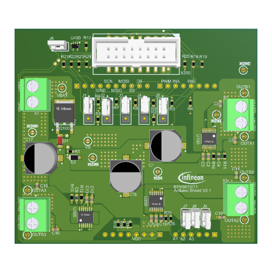
Figure 1
Board overview
This user guide introduces the features of the evaluation board MOTIX
Shield. It helps users evaluate hardware and software functionality of the MOTIX
Intended audience
This document is intended for engineers working with the MOTIX
Evaluation board
This board is used during design-in, for evaluation and measurement of characteristics, and proof of datasheet
specifications.
Related information
Related information
Table 1
Reference
Arduino UNO
Arduino IDE
uIO-Stick
full-bridge ICs BTM90xxEP Arduino
Full-bridge ICs BTM90xxEP Arduino
TM
TM
TM
full-bridge ICs BTM90xxEP.
Description
Information on Arduino UNO board
Details on Arduino IDE
Details on the debug interface
full-bridge ICs BTM90xxEP.
Advertisement
Table of Contents

Related Manuals for Infineon MOTIX BTM90 EP Series


Summary of Contents for Infineon MOTIX BTM90 EP Series
-
Page 1: About This Document
Z8F80497277 MOTIX full-bridge ICs BTM90xxEP Arduino Shield User guide About this document Scope and purpose Figure 1 Board overview This user guide introduces the features of the evaluation board MOTIX Full-bridge ICs BTM90xxEP Arduino Shield. It helps users evaluate hardware and software functionality of the MOTIX full-bridge ICs BTM90xxEP. -
Page 2: Important Notice
Infineon Technologies. The design of the evaluation boards and reference boards has been tested by Infineon Technologies only as described in this document. The design is not qualified in terms of safety requirements, manufacturing and operation over the entire operating temperature range or lifetime. -
Page 3: Safety Precautions
Due to technical requirements products may contain dangerous substances. For information on the types in question please contact your nearest Infineon Technologies office. Except as otherwise explicitly approved by Infineon Technologies in a written document signed by authorized representatives of Infineon Technologies, Infineon Technologies’ products may not be used in any applications where a failure of the product or any consequences of the use thereof can reasonably be expected to result in personal injury. -
Page 4: Table Of Contents
MOTIX full-bridge ICs BTM90xx Arduino Shield User guide Table of contents Table of contents About this document ........................1 Important Notice ..........................2 Safety precautions .......................... 3 Warnings ............................3 Table of contents ..........................4 MOTIX™ full-bridge ICs BTM90xxEP overview ................5 Key features ............................. -
Page 5: Motix™ Full-Bridge Ics Btm90Xxep Overview
MOTIX full-bridge ICs BTM90xxEP Arduino Shield User guide MOTIX™ full-bridge ICs BTM90xxEP overview The MOTIX™ full-bridge ICs BTM90xxEP are integrated full-bridges for DC motor control applications. BTM90xxEP is implemented in the BCD technology, and assembled in the PG-TSDSO-14 package, which has an exposed pad to achieve good thermal performance. - Page 6 MOTIX full-bridge ICs BTM90xxEP Arduino Shield User guide Device comparison BTM9010EP vs. BTM9011EP Table 2 BTM9010EP (HW variant) BTM9011EP (SPI variant) Package PG - TSDSO - 14 PG - TSDSO - 14 Digital interface INA, INB, SEL, PWM SDI, SCLK, CS, SDO Path resistance 175 mΩ...
-
Page 7: Block Diagram
MOTIX full-bridge ICs BTM90xxEP Arduino Shield User guide BTM9020EP (HW variant) BTM9021EP (SPI variant) Current sense Provided at IS pin Provided at IS pin Block diagram The MOTIX™ full-bridge ICs BTM90xxEP contains two half-bridges with an integrated MOSFET driver ICs implemented with a monolithic solution. -
Page 8: Pin Assignment
MOTIX full-bridge ICs BTM90xxEP Arduino Shield User guide Pin assignment Figure 4 Pin configuration of BTM9010EP/20EP Figure 5 Pin configuration of BTM9011EP/21EP User guide 8 of 24 Rev. 1.10 2024-06-18... -
Page 9: Introduction To The Evaluation Board
MOTIX full-bridge ICs BTM90xxEP Arduino Shield User guide Introduction to the evaluation board The board is designed to provide a simple, easy-to-use tool familiarize the designers with the MOTIX full- bridge ICs BTM90xxEP. Users can design the BDC motor control algorithms and test the designs on the board with Arduino UNO or with uIO-Stick. -
Page 10: Technical Data
MOTIX full-bridge ICs BTM90xxEP Arduino Shield User guide Protection schemes, e.g. against overtemperature and overcurrent • Reverse polarity protection • Watchdog (valid for BTM9021EP only) • Further comments: The size of the DC-link capacitor (C1 in the schematics and C in the application circuit.) at 330 µF rating •... -
Page 11: Application With Three Btm90X1Ep In Daisy-Chained Spi Control
MOTIX full-bridge ICs BTM90xxEP Arduino Shield User guide Using the uIO-Stick: place the pin header at J6. Connect only one pin header of J7-J9 • 2.4.2 Application with three BTM90x1EP in daisy-chained SPI control Figure 7 shows an example with three BTM9011EP/21EP devices connected in daisy-chained configuration reflected in configuration 1 and configuration 2, which is implemented in a DC motor control system. -
Page 12: Application With Daisy-Chain Spi Configuration And Direct Input
MOTIX full-bridge ICs BTM90xxEP Arduino Shield User guide 2.4.3 Application with daisy-chain SPI configuration and direct input Figure 9 shows the configuration 3 and 4 (default configuration), where two BTM9011EP/21EP devices connect in daisy-chain configuration and the microcontroller directly controls one BTM9010EP/20EP. With configuration 3 and 4, users can directly control one SPI variant BTM9010EP/20EP and the two pieces of the SPI variant BTM9011EP/21EP. - Page 13 MOTIX full-bridge ICs BTM90xxEP Arduino Shield User guide Figure 10 J1 – J6 pin header placement For more details of SPI and direct input settings of BTM90xxEP, refer to the datasheets. User guide 13 of 24 Rev. 1.10 2024-06-18...
-
Page 14: System And Functional Description
MOTIX full-bridge ICs BTM90xxEP Arduino Shield User guide System and functional description For the purpose of evaluation of DC motor control, discrete components are populated on board. They can be adapted to the dedicated motor control applications. Board information Find detailed information on the board in the tables below. Devices Table 6 Designator... -
Page 15: Arduino Uno Interface
MOTIX full-bridge ICs BTM90xxEP Arduino Shield User guide Pins connectors to Arduino UNO Table 10 Designator Connected to Connected to Description BTM90xxEP Arduino pin + 5 V Logic input of BTM90xxEP from Arduino UNO A1, A2, A3 D14, A15, D16 Analog input of Arduino UNO for current sensing and error... -
Page 16: Design Files
MOTIX full-bridge ICs BTM90xxEP Arduino Shield User guide Design files Schematics Figure 11 MOTIX full-bridge ICs BTM901xxEP Arduino Shield schematics User guide 16 of 24 Rev. 1.10 2024-06-18... -
Page 17: Layout
MOTIX full-bridge ICs BTM90xxEP Arduino Shield User guide Layout Figure 12 MOTIX full-bridge ICs BTM901xxEP Arduino Shield layer 1 (top layer) Figure 13 MOTIX full-bridge ICs BTM901xxEP Arduino Shield layer 2 (bottom layer) User guide 17 of 24 Rev. 1.10 2024-06-18... -
Page 18: Bill Of Material
MOTIX full-bridge ICs BTM90xxEP Arduino Shield User guide Bill of material BOM of Table 11 MOTIX full-bridge ICs BTM90xxEP Arduino Shield Designator Description Quantity Footprint C1, C17, C18 CAP / ELCO / 560uF / 35V / 20% / - / -55°C to CAPAE1030X1050N 105°C / 10.30mm L X 10.30mm W X 10.50mm H / SMD / -... - Page 19 MOTIX full-bridge ICs BTM90xxEP Arduino Shield User guide Designator Description Quantity Footprint X102 CON-M-THT-TSW- Through-Hole .025 SQ Post Header, 2.54mm pitch, 6 pins, Vertical, Single row, 500V 108-15-G-S X103 CON-M-THT-TSW- Through-Hole .025 SQ Post Header, 2.54mm pitch, 10 pins, Vertical, Single row, 500V 108-15-G-S X200 CON-M-SMD-HTST-...
-
Page 20: Getting Started
MOTIX full-bridge ICs BTM90xxEP Arduino Shield User guide Getting started Getting started using Arduino UNO board 5.1.1 Hardware Follow the instructions below to get started: Choose brushed DC motors considering: • o The normal operation voltage of the board: 7 – 18 V o The extended operation voltage of the board: 4.5 - 40 V Remove the pin header at J6. -
Page 21: Getting Started Using Uio-Stick
5.2.2 Software To control the board with the uIO-Stick, please follow the steps below: Download and install the Infineon Developer Center Launcher • Search, install and start Config Wizard for MOTIX Full Bridge ICs in the Infineon Developer Center •... - Page 22 MOTIX full-bridge ICs BTM90xxEP Arduino Shield User guide Figure 16 Board selection view in Config Wizard User guide 22 of 24 Rev. 1.10 2024-06-18...
-
Page 23: Revision History
MOTIX full-bridge ICs BTM90xxEP Arduino Shield User guide Revision history Document Date of release Description of changes version 1.10 2024-06-18 • Update according to new board design • Editorial changes 1.00 2023-10-13 • Initial Release User guide 23 of 24 Rev. - Page 24 Infineon Technologies hereby disclaims dangerous substances. For information on the types © 2024 Infineon Technologies AG. any and all warranties and liabilities of any kind in question please contact your nearest Infineon All Rights Reserved. (including without limitation warranties of non- Technologies office.
Need help?
Do you have a question about the MOTIX BTM90 EP Series and is the answer not in the manual?
Questions and answers