Table of Contents
Advertisement
Quick Links
AN113539
BGT24ATR22 YPA shield
XENSIV™ 24 GHz radar system platform
Board version V1.4
About this document
Scope and purpose
This application note describes the function, circuitry, and performance of the XENSIV™ BGT24ATR22 24 GHz
radar Yagi patch antenna (YPA) shield. The shield is the demo platform that accompanies Infineon's XENSIV™
BGT24ATR22 24 GHz radar sensor with an external pair of patch antennas, and one pair of Yagi antennas. The
shield offers a digital interface for configuration and transfer of the acquired radar data to a microcontroller
board such as Radar Baseboard MCU7.
Intended audience
This document is intended for design engineers, technicians, and developers of electronic systems, working
with Infineon's XENSIV™ BGT24ATR22 24 GHz low-power radar sensor.
Application note
Please read the sections "Important notice" and "Warnings" at the end of this document
Revision 1.00
www.infineon.com
2024-06-13
Advertisement
Table of Contents

Related Manuals for Infineon XENSIV BGT24ATR22 YPA shield


Summary of Contents for Infineon XENSIV BGT24ATR22 YPA shield
-
Page 1: About This Document
This application note describes the function, circuitry, and performance of the XENSIV™ BGT24ATR22 24 GHz radar Yagi patch antenna (YPA) shield. The shield is the demo platform that accompanies Infineon’s XENSIV™ BGT24ATR22 24 GHz radar sensor with an external pair of patch antennas, and one pair of Yagi antennas. The shield offers a digital interface for configuration and transfer of the acquired radar data to a microcontroller board such as Radar Baseboard MCU7. -
Page 2: Table Of Contents
BGT24ATR22 YPA shield XENSIV™ 24 GHz radar system platform Table of contents Table of contents About this document ........................1 Table of contents ..........................2 Introduction .......................... 3 24 GHz radar system platform ........................ 3 Key features ............................. 3 Hardware specifications ......................5 Overview .............................. -
Page 3: Introduction
The 24 GHz radar system platform described in this application note demonstrates the operational parameters of Infineon’s BGT24ATR22 24 GHz radar MMIC. The platform consists of two boards: the RF shield containing the MMIC and antennas, and Radar Baseboard MCU7. - Page 4 BGT24ATR22 YPA shield XENSIV™ 24 GHz radar system platform 1 Introduction Integrated analog baseband amplifiers • Automatic DC offset compensation • Integrated 12-bit ADC • Fully ESD-protected device • VQFN32-9 plastic package • Figure 2 Block diagram of BGT24ATR22 Application note Revision 1.00 2024-06-13...
-
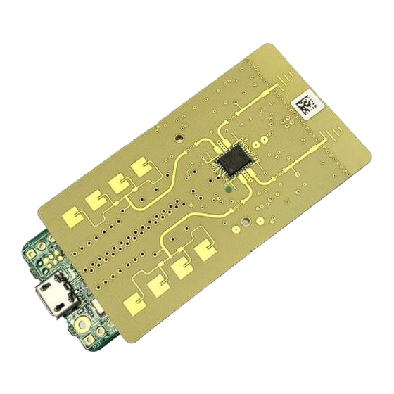
Page 5: Hardware Specifications
BGT24ATR22 YPA shield XENSIV™ 24 GHz radar system platform 2 Hardware specifications Hardware specifications Overview Top view Bottom view 32 mm Figure 3 BGT24ATR22 YPA shield (top and bottom views) The BGT24ATR22 YPA shield has dimensions of 32 mm x 58.5 mm on a 4-layer board (see Section for details of the layer stack). -
Page 6: Schematics
BGT24ATR22 YPA shield XENSIV™ 24 GHz radar system platform 2 Hardware specifications Schematics Figure 4 Overview of the schematic of the shield Sensor supply BGT24ATR22 supports 1.8 – 3.3 V as VDD and GPIO voltages, dependent on whether 1.8 V or 3.3 V are supplied. A chip-internal LDO generates 1.5 V as VDD_D as the digital supply. -
Page 7: Oscillator
BGT24ATR22 YPA shield XENSIV™ 24 GHz radar system platform 2 Hardware specifications Figure 5 External LDO generating 1.8 V output as VDD (VDD_RF, VDD_VCO, VDD_A) from 3.3 V input BGT24ATR22 is intended to be used in a heavy pulsed operational mode, showing high load transients for the supply current. -
Page 8: Connectors
BGT24ATR22 YPA shield XENSIV™ 24 GHz radar system platform 2 Hardware specifications Figure 7 Crystal and load capacitors Connectors On the BGT24ATR22 YPA shield, there are micro connectors for connecting the RF shield to Radar Baseboard MCU7 and pin headers for debugging. Figure 8 shows the two Hirose connectors that connect the RF shield to Radar Baseboard MCU7. -
Page 9: Eeprom And I2C Pull-Ups
BGT24ATR22 YPA shield XENSIV™ 24 GHz radar system platform 2 Hardware specifications EEPROM and I2C pull-ups Optionally, the BGT24ATR22 RF shield contains an EEPROM memory to store data such as the board identifier, with connections as shown in Figure 10. Note that even if the EEPROM is omitted, pull-up resistors must be placed on the I2C lines. -
Page 10: Layer Stackup
BGT24ATR22 YPA shield XENSIV™ 24 GHz radar system platform 2 Hardware specifications Layer stackup Figure 14 Layer stackup Surface finish is Electroless Nickel Immersion Gold (ENIG). Note: The RF shield design uses only through-hole vias. No blind vias are required. 2.10 Metal layers Figure 15... - Page 11 BGT24ATR22 YPA shield XENSIV™ 24 GHz radar system platform 2 Hardware specifications Figure 17 Layer 3 – Signal routing Figure 18 Bottom layer – Signal routing and supporting components Application note Revision 1.00 2024-06-13...
-
Page 12: Layout Overview
BGT24ATR22 YPA shield XENSIV™ 24 GHz radar system platform 3 Layout overview Layout overview Top side with MMIC and antennas λ/4 stub Matching structures Patch Yagi antennas antennas Pin 1 marking Additional ESD protection Figure 19 Layout elements on top side The top side features all the RF-related structures and the MMIC. -
Page 13: Mmic Footprint
BGT24ATR22 YPA shield XENSIV™ 24 GHz radar system platform 3 Layout overview 3.1.1 MMIC footprint It is recommended to use the exact footprint as shown in Figure 20 because this structure was optimized for use with BGT24ATR22 and recommended PCB material. Figure 20 Recommended PCB footprint Application note... -
Page 14: Patch Antennas
BGT24ATR22 YPA shield XENSIV™ 24 GHz radar system platform 3 Layout overview 3.1.2 Patch antennas The patch antennas are intended to be used during kick detection. Their radiation pattern is perpendicular to the RF shield’s surface. Figure 21 Simulated radiation pattern of patch antennas 3.1.3 Yagi antennas The Yagi antennas are intended for use during surveillance mode. -
Page 15: Bottom Side With Supporting Components
BGT24ATR22 YPA shield XENSIV™ 24 GHz radar system platform 3 Layout overview Bottom side with supporting components Connectors to RBB MCU7 Crystal Debug headers Figure 23 Components on bottom side All external components except the MMIC are placed on the bottom side of the RF shield. The main connector interface of the BGT24ATR22 YPA shield contains two Hirose DF40C-20DP-0.4V connectors. -
Page 16: References
BGT24ATR22 YPA shield XENSIV™ 24 GHz radar system platform References References [1] Infineon Technologies AG: AN599: Radar Baseboard MCU7; Available online Application note Revision 1.00 2024-06-13... -
Page 17: Revision History
BGT24ATR22 YPA shield XENSIV™ 24 GHz radar system platform Revision history Revision history Document Date Description of changes revision 1.00 2024-06-13 Initial version Application note Revision 1.00 2024-06-13... -
Page 18: Disclaimer
Infineon Technologies hereby Infineon Technologies’ products may not be used in disclaims any and all warranties and liabilities of any applications where a failure of the product or any any kind (including without limitation warranties of © 2024 Infineon Technologies AG.
Need help?
Do you have a question about the XENSIV BGT24ATR22 YPA shield and is the answer not in the manual?
Questions and answers