Table of Contents
Advertisement
Quick Links
Config Wizard Tool for
MOTIX™ single half-bridge IC's
BTN9970, BTN9990, BTN7030
User manual
About this document
Scope and purpose
This tool is a graphical user interface to control the motor control shields of Infineon's MOTIX
TM
single half-
bridge IC's BTN9970, BTN9990 and BTN7030.
With this tool two high current PN half bridges with integrated driver IC, BTN9970 and BTN9990, can be
controlled to drive e.g. brushed DC motors.
Intended audience
This document is addressed to embedded hardware and / or software developers which are familiar with motor
control schemes and intend to evaluate the IC'S BTN9970, BTN9990, BTN7030.
Please read the Important Notice and Warnings at the end of this document
10
www.infineon.com
page 1 of 16
2022-03-08
Advertisement
Table of Contents

Related Manuals for Infineon MOTIX BTN9970


Summary of Contents for Infineon MOTIX BTN9970
-
Page 1: About This Document
User manual About this document Scope and purpose This tool is a graphical user interface to control the motor control shields of Infineon’s MOTIX single half- bridge IC’s BTN9970, BTN9990 and BTN7030. With this tool two high current PN half bridges with integrated driver IC, BTN9970 and BTN9990, can be controlled to drive e.g. -
Page 2: Table Of Contents
Config Wizard Tool for MOTIX™ single half bridges BTN9970, BTN9990, BTN7030 Table of contents About this document ........................1 Table of contents ................Fehler! Textmarke nicht definiert. Setup for BTN9970 and BTN9990 ....................3 Open tool for BTN9970 and BTN9990 ..................6 Description of the graphical user interface BTN9970 and BTN9990 .......... -
Page 3: Setup For Btn9970 And Btn9990
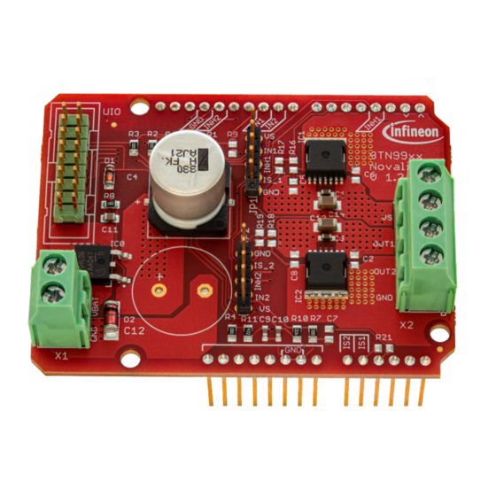
Config Wizard Tool for MOTIX™ single half-bridge IC’s BTN9970, BTN9990, BTN7030 BSL Tool for TLE988x/9x User Manual Setup for BTN9970 and BTN9990 Required hardware: IO Stick, see Figure 1. BTN9970 / BTN9990 motor control shield, see Figure 1, Figure 2 and Figure 3. 12V DC power supply, which is able to provide sufficient current for the motor load. - Page 4 Config Wizard Tool for MOTIX™ single half-bridge IC’s BTN9970, BTN9990, BTN7030 BSL Tool for TLE988x/9x User Manual pin header DC link I/O signals Capacitor (BTN9990) of IC1 Connector Connector X2 OUT1 (BTN9990) OUT2 (BTN9970) Connector X1 IC0 (PMOS) Reverse pin header (BTN9970) battery prot.
- Page 5 Config Wizard Tool for MOTIX™ single half-bridge IC’s BTN9970, BTN9990, BTN7030 BSL Tool for TLE988x/9x User Manual BTN9970/BTN9990 motor control shield Reverse battery protection Safety & Security Supply DC Link Capacitor BTN9970 BTN9990 - Driver - Driver - Diagnostic - Diagnostic Sensor OUT1 OUT2...
-
Page 6: Open Tool For Btn9970 And Btn9990
Config Wizard Tool for MOTIX™ single half-bridge IC’s BTN9970, BTN9990, BTN7030 BSL Tool for TLE988x/9x User Manual Open tool for BTN9970 and BTN9990 Select icon below to open the tool. Below screen will show up Application Note 6 of 16 2022-03-08... -
Page 7: Description Of The Graphical User Interface Btn9970 And Btn9990
Config Wizard Tool for MOTIX™ single half-bridge IC’s BTN9970, BTN9990, BTN7030 BSL Tool for TLE988x/9x User Manual Description of the graphical user interface for BTN9970 and BTN9990 Status LED for connection to IO Stick: Green indicates IO Stick is connected; Red indicates IO Stick is not connected Enable / Disable of the two half bridges BTN9990 (Half-Bridge 1)and BTN9970 (Half Bridge 2): If disabled, OUT 1 / 2 are high impedance. - Page 8 Config Wizard Tool for MOTIX™ single half-bridge IC’s BTN9970, BTN9990, BTN7030 BSL Tool for TLE988x/9x User Manual Sense Resistor Configuration BTN9990: In this field, the sense resistor of BTN9990 can be adapted in case it has been modified on the board. Default is 2k.
-
Page 9: Example For Btn9970 And Btn9990
Config Wizard Tool for MOTIX™ single half-bridge IC’s BTN9970, BTN9990, BTN7030 BSL Tool for TLE988x/9x User Manual Example for BTN9970 and BTN9990 The following example shows the configuration of the tool to drive a DC brush motor in a full bridge configuration, as shown in Figure 3. -
Page 10: Setup For Btn7030
Config Wizard Tool for MOTIX™ single half-bridge IC’s BTN9970, BTN9990, BTN7030 BSL Tool for TLE988x/9x User Manual Setup for BTN7030 Required hardware: IO Stick, see Figure 1. BTN7030 motor control shield, see Fehler! Verweisquelle konnte nicht gefunden werden.. 12V DC power supply, which is able to provide sufficient current for the motor load. Connections: Connect IO Stick to the BTN7030 motor control shield. - Page 11 Config Wizard Tool for MOTIX™ single half-bridge IC’s BTN9970, BTN9990, BTN7030 BSL Tool for TLE988x/9x User Manual Figure 6: Simplified application circuit for full brdige configuration with 2 x BTN7030as implemented on motor control shield Application Note 11 of 16 2022-03-08...
-
Page 12: Open Tool For Btn7030
Config Wizard Tool for MOTIX™ single half-bridge IC’s BTN9970, BTN9990, BTN7030 BSL Tool for TLE988x/9x User Manual Open tool for BTN7030 Select icon below to open the tool. BTN7030 Below screen will show up Application Note 12 of 16 2022-03-08... -
Page 13: Description Of The Graphical User Interface For Btn7030
Config Wizard Tool for MOTIX™ single half-bridge IC’s BTN9970, BTN9990, BTN7030 BSL Tool for TLE988x/9x User Manual Description of the graphical user interface for BTN7030 Enable / Disable of the two half bridges BTN7030 and diagnosis. If disabled, OUT 1 / 2 are high impedance. If enabled, status of OUT 1 / 2 pins depends on settings of IN1 and IN2 pin (Low, High, PWM). -
Page 14: References
Config Wizard Tool for MOTIX™ single half-bridge IC’s BTN9970, BTN9990, BTN7030 BSL Tool for TLE988x/9x User Manual If selected, the plot field area shows the IC1 sense current (half bridge 1 ) in the right graph and the corresponding IC1 load current in the left graph. The load current is calculated by the tool out of the IC1 sense current signal. -
Page 15: Revision History
Config Wizard Tool for MOTIX™ single half-bridge IC’s BTN9970, BTN9990, BTN7030 BSL Tool for TLE988x/9x User Manual Revision history Document Date of release Description of changes version 2022-03-24 First version Application Note 15 of 16 2022-03-08... - Page 16 Infineon Technologies hereby disclaims © 2022 Infineon Technologies AG. dangerous substances. For information on the types any and all warranties and liabilities of any kind in question please contact your nearest Infineon All Rights Reserved. (including without limitation warranties of non- Technologies office.
Need help?
Do you have a question about the MOTIX BTN9970 and is the answer not in the manual?
Questions and answers