Infineon XENSIV BGT60LTR11AIP EBG shield Manual
60 ghz radar system platform
Hide thumbs
Also See for XENSIV BGT60LTR11AIP EBG shield:
- User manual (55 pages) ,
- Manual (33 pages) ,
- User manual and instructions (15 pages)
Table of Contents
Advertisement
Quick Links
AN133733
BGT60LTR11AIP EBG shield
XENSIV™ 60 GHz radar system platform
Board version V3.1
About this document
Scope and purpose
This application note describes the function, circuitry, and performance of the XENSIV™ BGT60LTR11AIP 60 GHz
radar electromagnetic band gap (EBG) shield. The shield provides the supporting circuitry to the onboard
BGT60LTR11AIP monolithic microwave integrated circuit (MMIC), Infineon's 60 GHz radar chipset with antenna-
in-package (AIP). An EBG structure is added to reduce the impact of neighboring components, resulting in a
homogeneous field of view (FoV). This makes BGT60LTR11AIP the appropriate choice for ceiling-mounted
applications. In addition to the autonomous mode configuration, the shield offers a digital interface for
configuration and transfer of the acquired radar data to a microcontroller board such as Radar Baseboard
MCU7.
Intended audience
The intended audiences for this document are design engineers, technicians, and developers of electronic
systems, working with Infineon's XENSIV™ 60 GHz radar sensors.
Application note
Please read the sections "Important notice" and "Warnings" at the end of this document
Revision 1.10
www.infineon.com
2024-05-20
Advertisement
Table of Contents

Related Manuals for Infineon XENSIV BGT60LTR11AIP EBG shield


Summary of Contents for Infineon XENSIV BGT60LTR11AIP EBG shield
-
Page 1: About This Document
(EBG) shield. The shield provides the supporting circuitry to the onboard BGT60LTR11AIP monolithic microwave integrated circuit (MMIC), Infineon’s 60 GHz radar chipset with antenna- in-package (AIP). An EBG structure is added to reduce the impact of neighboring components, resulting in a homogeneous field of view (FoV). -
Page 2: Table Of Contents
BGT60LTR11AIP EBG shield XENSIV™ 60 GHz radar system platform Table of contents Table of contents About this document ........................1 Table of contents ..........................2 Introduction .......................... 3 60 GHz radar system platform ........................ 3 Key features ............................. 4 System specifications ......................5 Hardware description ...................... -
Page 3: Introduction
The BGT60LTR11AIP electromagnetic band gap (EBG) shield demonstrates the features of the BGT60LTR11AIP MMIC and gives you a “plug-and-play” radar solution. The shield can also be attached to an Arduino MKR board or an Infineon Radar Baseboard MCU7. A graphical user interface (GUI) is available via Developer Center display and analyze the acquired data in the time and frequency domains. -
Page 4: Key Features
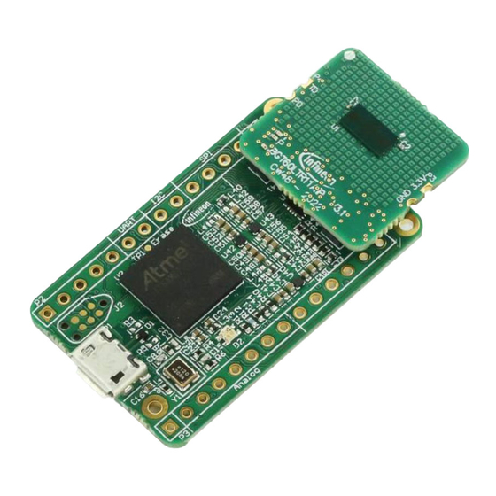
BGT60LTR11AIP EBG shield XENSIV™ 60 GHz radar system platform Introduction BGT60LTR11AIP Demo BGT60LTR11AIP MMIC BGT60LTR11AIP EBG shield = Radar Baseboard MCU7 + BGT60LTR11AIP EBG shield 20.20 mm Figure 1 BGT60LTR11AIP EBG shield using BGT60LTR11AIP MMIC Key features The BGT60LTR11AIP EBG shield is optimized for fast prototyping design and system integration, as well as initial product feature evaluation. -
Page 5: System Specifications
BGT60LTR11AIP EBG shield XENSIV™ 60 GHz radar system platform System specifications System specifications Table 1 BGT60LTR11AIP EBG shield specifications Parameter Unit Min. Typ. Max. Comments System performance Detection range – Typical motion detection range for human target at low threshold (in both E-plane and H-plane orientations) Power supply... -
Page 6: Hardware Description
BGT60LTR11AIP EBG shield XENSIV™ 60 GHz radar system platform Hardware description Hardware description Overview The BGT60LTR11AIP EBG shield is a very small PCB of 20.2 mm x 19.15 mm size, with a XENSIV™ BGT60LTR11AIP 60 GHz radar sensor mounted on top of the PCB. The PCB can be manufactured using a standard FR4 laminate, as the antennas are integrated into the chip package. -
Page 7: Bgt60Ltr11Aip Mmic
BGT60LTR11AIP EBG shield XENSIV™ 60 GHz radar system platform Hardware description 1.5V_RF 1.8 V or 3.3 V 1.5V_PLL 3.3 V Castellated Holes 1.5V_RF PDet LED2 1.5V_RF TDet LED1 38.4 MHz EEPROM quartz Figure 4 BGT60LTR11AIP EBG shield block diagram The block diagram in Figure 4 shows the configuration of the shield. - Page 8 BGT60LTR11AIP EBG shield XENSIV™ 60 GHz radar system platform Hardware description A low-pass filter (LPF) • The integrated target detector circuits in the MMIC indicate the detection of movement in front of the radar and the direction of movement with two digital signals (BGT_TARGET_DET and BGT_PHASE_DET). See Section for more details.
-
Page 9: Sensor Power Supply
BGT60LTR11AIP EBG shield XENSIV™ 60 GHz radar system platform Hardware description Top view Side view Bottom view Figure 7 Top, side, and bottom views of the BGT60LTR11AIP MMIC package – all dimensions in mm Sensor power supply Because radar sensors are very sensitive to supply voltage fluctuations or crosstalk between different supply domains, a low-noise power supply and properly decoupled supply rails are critical. -
Page 10: Crystal
BGT60LTR11AIP EBG shield XENSIV™ 60 GHz radar system platform Hardware description Crystal The MMIC requires an oscillator source with a stable reference clock providing low phase jitter and low phase noise; the oscillator is integrated inside the MMIC. This reduces the current consumption because crystal oscillators consume only a few milliamperes (mA) and run continuously. - Page 11 BGT60LTR11AIP EBG shield XENSIV™ 60 GHz radar system platform Hardware description The charging time of the hold capacitor ( is limited to the selected PW. Shorter PWs require smaller �� �� ℎ������ ℎ������ to become ~90% percent charged during one pulse. The rise time is controlled by the itself and the ��...
-
Page 12: Connectors
BGT60LTR11AIP EBG shield XENSIV™ 60 GHz radar system platform Hardware description Connectors The BGT60LTR11AIP EBG shield can be connected to an MCU board like Radar Baseboard MCU7 with the P1 and P2 connectors. Castellated holes (P3 and P4) are visible on the top and bottom sides of the PCB. TD and PD pins of the castellated holes correspond to the internal detector outputs of the MMIC. -
Page 13: Leds And Level Shifters
BGT60LTR11AIP EBG shield XENSIV™ 60 GHz radar system platform Hardware description 3V3digital1 I2C_SCL I2C_SDA 24CW1280T-I/CS0668 3V3digital1 Figure 13 Schematics of the EEPROM LEDs and level shifters The shield has two LEDs to indicate the motion detection (green) and the target’s direction of motion (red); see Figure 14. -
Page 14: Mmic Quad-State Inputs
BGT60LTR11AIP EBG shield XENSIV™ 60 GHz radar system platform Hardware description MMIC quad-state inputs The BGT60LTR11AIP MMIC has four quad-state inputs QS1 to 4, used in autonomous mode to set the device configuration. Figure 15 shows the default settings of these QS pins on the BGT60LTR11AIP EBG shield. To offer more flexibility in autonomous mode, an “Advance mode”... - Page 15 BGT60LTR11AIP EBG shield XENSIV™ 60 GHz radar system platform Hardware description The EBG structure has two important effects; both effects result in fewer deviations of the initial radiation pattern by the PCB. Reflections of an electromagnetic wave traveling perpendicular to the surface of the EBG structure behave •...
-
Page 16: Layer Stackup And Routing
BGT60LTR11AIP EBG shield XENSIV™ 60 GHz radar system platform Hardware description 3.11 Layer stackup and routing The PCB is designed with a four-layer stackup with standard FR4 material. Figure 17 shows the different layers and their thicknesses. Figure 17 PCB layer stackup in 2D and 3D views In the routing on the PCB, the VTUNE pin on the BGT60LTR11AIP MMIC should be left floating. -
Page 17: Radar Mmic Configuration
BGT60LTR11AIP EBG shield XENSIV™ 60 GHz radar system platform Radar MMIC configuration Radar MMIC configuration The radar MMIC can be configured in two different operation modes. In autonomous mode, the sensor configuration parameters are set via QS pins and external resistors. In SPI mode, the connection to a microcontroller allows setting the sensor configuration parameters by writing in the internal registers through SPI. - Page 18 BGT60LTR11AIP EBG shield XENSIV™ 60 GHz radar system platform Radar MMIC configuration By default, the BGT60LTR11AIP EBG shield is configured in SPI mode to enable radar MMIC configuration via the FW running on the Radar Baseboard MCU7 microcontroller. To make the shield work in autonomous mode, you need to remove resistor R3, as shown in Figure Remove R3 for autonomous mode...
-
Page 19: Detector Threshold
BGT60LTR11AIP EBG shield XENSIV™ 60 GHz radar system platform Radar MMIC configuration Detector threshold The internal detector threshold is the minimum signal strength that must be reached to trigger a detection event. The lower the threshold set, the higher the sensitivity and therefore the higher the detection range. Note: To avoid triggering a false detection, increase the detector threshold, which reduces the sensor sensitivity, especially in “noisy”... -
Page 20: Detector Hold Time
BGT60LTR11AIP EBG shield XENSIV™ 60 GHz radar system platform Radar MMIC configuration Detector hold time The internal detector hold time is the time for which the internal detector outputs remain active after target detection. Autonomous mode QS3 is used to select the detector hold time value for autonomous mode. To have up to 16 hold time values, set “Advance mode”, as explained in 4.2. -
Page 21: Operating Frequency
BGT60LTR11AIP EBG shield XENSIV™ 60 GHz radar system platform Radar MMIC configuration Operating frequency Autonomous mode QS4 is used to set the operating frequency for the MMIC in the 60 GHz ISM band, which is important to meet worldwide regulation requirements. See Table 7 for possible settings. -
Page 22: Pulse Repetition Time (Prt)
BGT60LTR11AIP EBG shield XENSIV™ 60 GHz radar system platform Radar MMIC configuration Pulse repetition time (PRT) PRT is the duty cycle repetition rate, which means the time until the next pulsing sequence starts in pulsed mode. Autonomous mode The PRT can be configured in autonomous pulsed mode (QS1 is either GND or OPEN, as shown in Table 4) only if “Advance mode”... -
Page 23: Autonomous Mode Operation
Figure Shield castellated holes Arduino pins Figure 22 Radar shield mounted on an Arduino MKR Wifi1010 board Find the BGT60LTR11 Radar Arduino Library and instructions to get started on Infineon’s GitHub repository. Application note Revision 1.10 2024-05-20... -
Page 24: Firmware
BGT60LTR11AIP EBG shield XENSIV™ 60 GHz radar system platform Firmware Firmware Overview Radar Baseboard MCU7 comes with a default FW that serves as a bridge between a host (typically a PC) and the BGT60LTR11AIP RF shield mounted on sensor connectors. When the FW detects a BGT60LTR11AIP EBG shield, it automatically configures the driver layer for the BGT60LTR11AIP sensor. - Page 25 BGT60LTR11AIP EBG shield XENSIV™ 60 GHz radar system platform Firmware Activate falling-edge IRQ. 2. After the falling edge on the MISO line: Deactivate the falling-edge IRQ. MCU SPI communication allowed. Start the readout of internal ADC registers (Reg40 and Reg41) if required. Perform other SPI register access operations.
- Page 26 BGT60LTR11AIP EBG shield XENSIV™ 60 GHz radar system platform Firmware Start Hard-Reset or Soft-Reset Wait 1.5 msec Access SPI registers during runtime? Setup registers Guard Timer Activate miso_drv (Reg15[6]) Activate Pulse or CW mode expires Setup registers Guard timer expired Activate Pulse or CW mode Block access to SPI Enable IRQ for raising edge...
- Page 27 BGT60LTR11AIP EBG shield XENSIV™ 60 GHz radar system platform Firmware Note the following: MISO line is High-Z if Chip Select (CS) is inactive (default). • MISO arbitration can be enabled via the miso_drv (Reg15[6]) bit. • Without respecting MISO arbitration, device functionality is NOT ensured. •...
-
Page 28: Measurement Results
BGT60LTR11AIP EBG shield XENSIV™ 60 GHz radar system platform Measurement results Measurement results Radiation pattern simulation results To analyze the sensor radiation characteristics, the radiation pattern of a BGT60LTR11AIP EBG shield configured in CW mode is simulated along the H-plane and E-plane of the sensor. Figure 26a shows the realized gain of the transmitting antenna in H-plane and E-plane at a frequency of 61 GHz. -
Page 29: Motion Detection Area
BGT60LTR11AIP EBG shield XENSIV™ 60 GHz radar system platform Measurement results Motion detection area The measurements are conducted for different MMIC operation modes and settings. Figure 28 shows the possible operating modes, and how the detection status is driven. Sample QS pins Autonomous mode SPI mode inputs... -
Page 30: Spi Mode And Mmic Internal Detector
BGT60LTR11AIP EBG shield XENSIV™ 60 GHz radar system platform Measurement results H-plane E-plane Figure 29 H-plane and E-plane human target detection area for BGT60LTR11AIP autonomous shield 7.2.2 SPI mode and MMIC internal detector Hardware • Radar Baseboard MCU7 and BGT60LTR11AIP EBG shield (by default, configured in SPI pulsed mode). Firmware •... -
Page 31: Spi Mode And Motion Detection Algorithm
BGT60LTR11AIP EBG shield XENSIV™ 60 GHz radar system platform Measurement results Figure 31 E-plane human target detection area, in SPI mode, using MMIC internal detector 7.2.3 SPI mode and motion detection algorithm Hardware • Radar Baseboard MCU7 and BGT60LTR11AIP EBG shield (by default, configured in SPI pulsed mode). Firmware •... -
Page 32: On-Ceiling Measurements
BGT60LTR11AIP EBG shield XENSIV™ 60 GHz radar system platform Measurement results H-plane E-plane Figure 32 H-plan and E-plane human target detection area, in SPI mode, using advanced motion sensing (AMS) algorithm 7.2.4 On-ceiling measurements Hardware • Radar Baseboard MCU7 and BGT60LTR11AIP EBG shield (by default, configured in SPI pulsed mode). Firmware •... - Page 33 BGT60LTR11AIP EBG shield XENSIV™ 60 GHz radar system platform Measurement results 0° 270° AMS (Thres. = 15) 90° Internal detectors (Thres. = 80) 180° Figure 33 On-ceiling measurement results in SPI mode using the radar internal detectors (in red) and the AMS algorithm (in blue) Application note Revision 1.10...
-
Page 34: Power Consumption Analysis
BGT60LTR11AIP EBG shield XENSIV™ 60 GHz radar system platform Power consumption analysis Power consumption analysis Duty cycling The current consumption of the BGT60LTR11AIP MMIC can be optimized by configuring the duty cycle pulse width (PW) and pulse repetition time (PRT). Table 9 lists the current consumption values of the MMIC with the default PW of 5 µs (the time MMIC is active during one pulsing event). -
Page 35: Adaptive Pulse Repetition Time (Aprt)
BGT60LTR11AIP EBG shield XENSIV™ 60 GHz radar system platform Power consumption analysis Adaptive pulse repetition time (APRT) APRT is a power-saving option of the BGT60LTR11AIP MMIC. It consists of multiplying the PRT by a factor of 2, 4, 8, or 16 when no target is detected by the internal detector. When a target is detected, the PRT returns to the default value to ensure reliable detection. - Page 36 BGT60LTR11AIP EBG shield XENSIV™ 60 GHz radar system platform Power consumption analysis Figure 37 APRT enabled: Multiplier x16, no target detected; PRT switches to 8 ms Figure 38 APRT enabled: Multiplier x16, target detected; PRT switches back from 8 ms to 500 µs Application note Revision 1.10 2024-05-20...
-
Page 37: References
Available online Infineon Technologies AG. User’s guide to BGT60LTR11AIP; Available online Infineon Technologies AG. Radar Baseboard MCU7 application note; Available online Infineon Technologies AG. Electronic band gap (EBG) structure for BGT60LTR11AIP application note; Available online Application note Revision 1.10 2024-05-20... -
Page 38: Revision History
BGT60LTR11AIP EBG shield XENSIV™ 60 GHz radar system platform Revision history Revision history Document Date Description of changes revision 1.00 2023-02-14 Initial version 1.10 2024-05-20 Updated Figure 24. SPI arbitration flow diagram to fix miso_drv register number Updated Figures 15, 18, 19 with the shield v3.1 details instead of v2.0 Miscellaneous document cleanup updates Application note Revision 1.10... -
Page 39: Disclaimer
Infineon Technologies hereby Infineon Technologies’ products may not be used in disclaims any and all warranties and liabilities of any applications where a failure of the product or any any kind (including without limitation warranties of © 2024 Infineon Technologies AG.
Need help?
Do you have a question about the XENSIV BGT60LTR11AIP EBG shield and is the answer not in the manual?
Questions and answers