Table of Contents
Advertisement
Quick Links
Demoboard BTS3011TE User Manual V1.0
Demoboard BTS3011TE
User Manual
About this document
Scope and purpose
This document describes how to use the Demoboard BTS3011TE
Intended audience
Engineers, hobbyists and students who want to switch 12V loads in their Arduino UNO projects or evaluate the
performances of the BTS3011TE with usual lab equipements (waveform generator, power supply, etc... )
Table of contents
About this document ....................................................................................................................... 1
Table of contents ............................................................................................................................ 1
1
Getting Started ...................................................................................................................... 3
1.1
BTS3011TE Shield Overview ................................................................................................................... 3
1.3
Key Features ............................................................................................................................................ 4
1.4
Demoboard Package Contents ............................................................................................................... 4
1.5
Typical Connection ................................................................................................................................. 4
1.5.1
With Arduino UNO Shield ................................................................................................................... 4
1.5.2
Without Arduino UNO ........................................................................................................................ 4
2
Demoboard Configuration ....................................................................................................... 5
2.1
STATUS Pin Connection .......................................................................................................................... 5
2.1.1
Overcurrent limitation / Short circuit behavior ................................................................................ 6
2.1.3
Behavior with overload current below current limitation trigger level ........................................... 7
3
Software Utilisation ............................................................................................................... 8
3.1
Installation ............................................................................................................................................... 8
3.2
Features ................................................................................................................................................... 8
3.2.1
Overview Panel ................................................................................................................................... 8
3.2.2
Control Panel ...................................................................................................................................... 9
3.2.4
Alternative Command Panel ............................................................................................................ 10
4
Board Connector Description .................................................................................................. 11
4.1
Power Connector ................................................................................................................................... 11
4.2
Arduino/XMC1100 Connectors .............................................................................................................. 11
4.2.1
Connector SV1 .................................................................................................................................. 11
4.2.2
Connector SV2 .................................................................................................................................. 12
4.2.3
Connector SV3 .................................................................................................................................. 12
4.2.4
Connector SV4 .................................................................................................................................. 12
4.4
Push Buttons and Jumper .................................................................................................................... 13
4.4.1
Push Button SW1 / SW2.................................................................................................................... 13
4.4.2
Jumper JP8 ...................................................................................................................................... 13
4.5
Test Points ............................................................................................................................................. 13
5
Schematic ............................................................................................................................ 14
User guide
www.infineon.com
Please read the Important Notice and Warnings at the end of this document
page 1 of 19
Revision 1.0
2019-05-07
Advertisement
Table of Contents

Related Manuals for Infineon BTS3011TE


Summary of Contents for Infineon BTS3011TE
-
Page 1: Table Of Contents
Intended audience Engineers, hobbyists and students who want to switch 12V loads in their Arduino UNO projects or evaluate the performances of the BTS3011TE with usual lab equipements (waveform generator, power supply, etc… ) Table of contents About this document ........................1 Table of contents .......................... - Page 2 Demoboard BTS3011TE User Manual Getting Started B.O.M ........................... 15 Board Layout ........................16 TOP................................. 16 BOTTOM ..............................16 MECHANICAL VIEW ..........................17 Revision history..........................18 User guide 2 of 19 Revision 1.0 2019-05-07...
-
Page 3: Getting Started
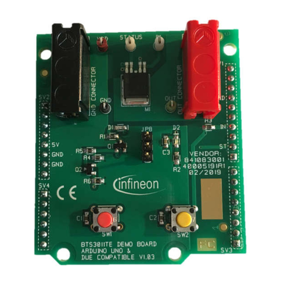
Getting Started BTS3011TE Shield Overview The 12V low-side switch demoboard with one BTS3011TE from Infineon Technologies is a flexible evaluation board dedicated to drive all kinds of loads up to 1kHz, especially motors and capacitive-like loads. This demoboard is compatible with Arduino UNO shield. -
Page 4: Key Features
Demoboard BTS3011TE User Manual Getting Started Key Features Demoboard is able to provide continuous current load (20A in DC mode) between V_OUT and GND • A green LED will light on when logic supply voltage is connected and ON •... -
Page 5: Demoboard Configuration
If an Arduino is used, configuration needs to be set in the software. Please refer to 3.2.2 Control Panel. STATUS Pin Connection BTS3011TE can be controlled with STATUS pin pulled-up to VDD to allow fault monitoring, Figure 4 shows the two possible settings of for STATUS pin... -
Page 6: Overcurrent Limitation / Short Circuit Behavior
Demoboard BTS3011TE User Manual Demoboard Configuration STATUS pin functionality Table 1 Symbol Function STATUS Input Reset of latches by microcontroller pull-up Output “high”: Normal operation “low”: Overtemperature condition 2.1.1 Overcurrent limitation / Short circuit behavior If the load current I... -
Page 7: Behavior With Overload Current Below Current Limitation Trigger Level
Demoboard BTS3011TE User Manual Demoboard Configuration 2.1.3 Behavior with overload current below current limitation trigger level The lower current limitation level I will be also triggered by a thermal shutdow. This could be the case in L(LIM) terms of overload with a current still beliw the current limitation trigger lever (I <... -
Page 8: Software Utilisation
“Demoboard_Aiko_Universal.ino” Arduino code and upload it. When the code is correctly uploaded / installed, the user can plug the demoboard on the Arduino shield. The • green LED must turn-on, meaning that BTS3011TE logic is supplied Then, launch the “Demoboard_Aiko_Universal.exe”. •... -
Page 9: Control Panel
If BTS3011TE operates normally, Vstatus should appear in green. − If BTS3011TE is latched, status appears in red. 3.2.2 Control Panel Button “ON/OFF” allows the user to switch ON and OFF the BTS3011TE in continuous mode. • Button “Pulse” creates a manageable pulse for the BTS3011TE. • −... -
Page 10: Alternative Command Panel
Demoboard BTS3011TE User Manual Software Utilisation 3.2.4 Alternative Command Panel STATUS pin can be reseted (Low to High) when Reset Status button is pressed • Current limitation threshold can be reset when Reset Trig buttion is pressed • Figure 9... -
Page 11: Board Connector Description
Demoboard BTS3011TE User Manual Board Connector Description Board Connector Description Figure 10 Connectors implantation Power Connector Table A Table 2 Name Connector Type Description Power supply OUT Connector Ground power GND Connector Arduino/XMC1100 Connectors 4.2.1 Connector SV1 Table A Table 3... -
Page 12: Connector Sv2
Demoboard BTS3011TE User Manual Board Connector Description 4.2.2 Connector SV2 Table A Table 4 Name Connector Type Description 1 to 4 Not connected Logic supply Digital Ground Ground Digital Ground Ground Not connected 4.2.3 Connector SV3 Table A Table 5... -
Page 13: Push Buttons And Jumper
Digital input Pin Activation for BTS3011TE STATUS Digital I/O Pin to monitor the part status Logic supply Pin to provide supply to BTS3011TE Logic ( 5V recommended) Analog output Pin to monitor V_OUT Analog input Pin to monitor the GND... -
Page 14: Schematic
Demoboard BTS3011TE User Manual Schematic Schematic Figure 11 Example figure User guide 14 of 19 Revision 1.0 2019-05-07... -
Page 15: O.m
Demoboard BTS3011TE User Manual B.O.M B.O.M Table A Table 10 Item Quantity Reference Part "C1,C3" 100n RED LED GREEN LED HEADER 3 "TP1,J1" "TP2,J2" BTS3011TE PMOS1 PMOS2 "R1,R2" "SV1,SV2,SV3,SV4" CONNECTOR EDGE 10 "SW1,SW2" SW_TC_SPST STATUS User guide 15 of 19 Revision 1.0... -
Page 16: Board Layout
Demoboard BTS3011TE User Manual Board Layout Board Layout Figure 12 Example figure Body text. BOTTOM User guide 16 of 19 Revision 1.0 2019-05-07... -
Page 17: Mechanical View
Demoboard BTS3011TE User Manual Board Layout Figure 13 xample figure MECHANICAL VIEW Figure 14 Example figure User guide 17 of 19 Revision 1.0 2019-05-07... -
Page 18: Revision History
Demoboard BTS3011TE User Manual Revision history Revision history Document Date of release Description of changes version May 7, 2019 First release User guide 18 of 19 Revision 1.0 2019-05-07... - Page 19 Infineon Technologies hereby disclaims dangerous substances. For information on the types © 2022 Infineon Technologies AG. any and all warranties and liabilities of any kind in question please contact your nearest Infineon All Rights Reserved. (including without limitation warranties of non- Technologies office.
Need help?
Do you have a question about the BTS3011TE and is the answer not in the manual?
Questions and answers