Sign In
Upload
Manuals
Brands
Quantech Manuals
Chiller
QTC40250
Quantech QTC40250 Manuals
Manuals and User Guides for Quantech QTC40250. We have
1
Quantech QTC40250 manual available for free PDF download: Installation Operation & Maintenance
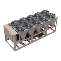
Quantech QTC40250 Installation Operation & Maintenance (188 pages)
Air-Cooled Screw Liquid Chillers with Variable Speed Drive
Brand:
Quantech
| Category:
Chiller
| Size: 6.67 MB
Table of Contents
Table of Contents
6
Section 1 - General Chiller Information and Safety
11
Introduction
11
Warranty
11
Quality Assurance and Safety
12
Fluorinated Greenhouse Gases
12
Responsibility for Safety
12
About this Manual
12
Misuse of Equipment
12
Section 2 - Product Description
15
General System Description
15
Figure 1 - QTC4 Air-Cooled Screw Liquid Chiller with Variable Speed Drive
15
Figure 2 - Chiller Control System
16
Semi-Hermetic Quantech Twin-Screw Compressors
17
Evaporator
17
Condenser
17
Refrigerant Circuit
17
Electrical
17
Building Automation System Capabilities
18
Microcomputer Control Center
18
Accessories and Options
19
Fan Options
19
Condenser Coils
19
Figure 3 - View of Quantech Control Center User Interface
19
Section 3 - Rigging, Handling, and Storage
23
Lifting Weights
23
Delivery and Storage
23
Inspecting the Delivery
24
Moving the Chiller
24
Figure 4 - Lifting Lugs
24
Figure 5 - Lifting Using Lugs
24
Figure 6 - Power Panel. 1 to 4
25
Table 1 - Unit Lifting Point Locations
25
Figure 7 - Power Panel, 1 to 5
26
Figure 8 - Power Panel, 1 to 6
27
Figure 9 - Power Panel, 1 to 8
28
Section 4 - Installation
29
Location Requirements
29
Outdoor Installations
29
Location Clearances
29
Figure 10 - Acceptable Minimum Clearances Around and between Units
30
Table 2 - Minimum Evaporator Tube Removal Clearance
30
Vibration Isolators
31
Shipping Braces
31
Chilled Liquid Piping
31
Evaporator Pressure Drop
32
Water Treatment
33
Pipework Arrangement
33
Minimum Water Volume
33
Leaving Water Temperature out of Range
33
Figure 11 - Pipework Arrangement
33
Figure 12 - Leaving Water Temperature out of Range Suggested Layout
33
Thermal Storage
34
Variable Primary Flow
34
Connection Types and Sizes
34
Evaporator Connections
34
Figure 13 - Suggested Layout for Applications with a Flow Rate Less than the Evaporator Minimum
34
Figure 14 - Suggested Layout for Applications with a Flow Rate Greater than the Evaporator Maximum
34
Figure 15 - Grooved Nozzle
34
Table 3 - Evaporator Connections Dimensions
35
Refrigerant Relief Valve Piping
36
Electrical Connection
36
Figure 16 - Flange for GB Vessels
36
Figure 17 - Flange Attachment
36
Power Wiring
37
Power Supply Wiring
37
115 VAC Control Supply Transformer
37
Control Wiring
37
Volts Free Contacts
38
System Inputs
38
Power Supply Wiring
39
Figure 18 - Single Point Power Wiring
39
Figure 19 - Dual Point Power Wiring
40
Customer Control Wiring
41
Figure 20 - Customer Control Connections
41
Thermal Dispersion Flow Switch Connections
42
Figure 21 - Thermal Dispersion Flow Switch Connections
42
Figure 22 - Reserved Customer Wiring Entry
43
Figure 23 - Water Box Heater Wiring Box
43
Table 4 - Standard 2 Hp Condenser Fans, Single Point Electrical Lug Data
45
Table 5 - Standard 2 Hp Condenser Fans, Dual Point Electrical Lug Data
53
Table 6 - EBM Condenser Fans, Single Point Electrical Lug Data
55
Table 7 - EBM Condenser Fans, Dual Point Electrical Lug Data
63
Section 5 - Technical Data
65
Table 8 - Physical Data, Microchannel Coil
66
Figure 24 - Standard Two-Pass, Right Side Inlet/Outlet Evaporator Connections
70
Table 9 - Standard Two-Pass, Right Side Inlet/Outlet Evaporator Connections
70
Figure 25 - Optional Two-Pass Left Side Inlet/Outlet Connections
72
Table 10 - Optional Two-Pass Left Side Inlet/Outlet Connections
72
Figure 26 - Standard Two-Pass Left Side Inlet/Outlet Connections
74
Table 11 - Standard Two-Pass Left Side Inlet/Outlet Connections
74
Figure 27 - Optional Three-Pass Inlet/Outlet Connections
75
Table 12 - Optional Three-Pass Inlet/Outlet Connections
75
Figure 28 - QTC4 Dimensions
77
Figure 29 - Isolator Selection and Mounting Locations
78
Table 13 - Isolator Selection and Mounting Locations
78
Figure 30 - Isolator Selection and Mounting Locations
79
Figure 31 - Isolator Selection and Mounting Locations
80
Figure 32 - Isolator Selection and Mounting Locations
81
Figure 33 - Isolator Selection and Mounting Locations
82
Figure 34 - Isolator Selection and Mounting Locations
83
Figure 35 - Isolator Selection and Mounting Locations
84
Figure 36 - Isolator Selection and Mounting Locations
85
Figure 37 - Isolator Selection and Mounting Locations
86
Figure 38 - Isolator Selection and Mounting Locations
87
Elastomeric Isolator Installation
88
Figure 39 - Elastomeric Isolator
88
Elastomeric Isolator Specifications
89
Figure 40 - Elastomeric Isolator Specifications
89
Table 14 - Elastomeric Dimensions
89
Table 15 - Elastomeric Weights
89
One Inch Deflection Isolator Installation
90
Figure 41 - One Inch Deflection Isolator
90
One Inch Deflection Spring Isolator Specifications
91
Figure 42 - One Inch Deflection Isolator Specifications
91
Table 16 - One Inch Deflection Isolator Dimensions
91
Table 17 - One Inch Deflection Isolator Weights
91
Two Inch Deflection, Isolator Installation and Adjustment
92
Figure 43 - Two Inch Deflection Isolator
92
Two Inch Deflection, Restrained Spring Isolator Specifications
93
Figure 44 - Two Inch Deflection Isolator Specifications
93
Table 18 - Two Inch Deflection Isolator Weights
93
Section 6 - Commissioning
95
Preparation
95
Figure 45 - LED Indicator Buttons
96
Figure 46 - Flow Switch Set
97
Figure 47 - Flow below the Representation Range
97
Figure 48 - Flow Exceeds the Representation Range
97
First Time Startup
98
General Operation
98
Freeze Damage Protection
98
Table 19 - QTC4 Freeze Damage Protection Requirements
99
Section 7 - Operation
101
Operating Controls
101
Figure 49 - Keyboard and Display
101
Basic Operating Sequence
104
Microboard (331-03478-XXX)
104
Figure 50 - New 331-03478-XXX Microboard
106
SC-EQ Communications Card
107
Updating the Program
107
Data Logging
108
Table 20 - Flash Card Update Error XXXXX
108
Unit Warning
109
Unit Safeties
110
System Safeties, Faults
111
Table 21 - Low Differential Oil Pressure Cutout
113
Table 22 - Discharge Pressure Load Limiting/Unloading
114
Table 23 - Suction Pressure Load Limiting/Unloading
114
Table 24 - Start Inhibit Sensor Thresholds
115
Section 8 - Micropanel
117
Figure 51 - Micropanel
117
Unit Data Key
120
Figure 52 - Unit Data Key
120
System Data Keys 1 through 4
122
Figure 53 - System Data Keys 1 through 4
122
Table 25 - System Sensor Minimum and Maximum Outputs
124
VSD Data Key
125
Figure 54 - VSD Data Key
125
Table 26 - Compressor Overload Settings
126
Operating Hours/Start Counter Key
127
Figure 55 - Operating Hours/Start Counter Key
127
History Key
128
Figure 56 - History Key
128
Setpoints Key
135
Figure 57 - Setpoints Key
135
Table 27 - Setpoint Limits
136
Program Key
137
Figure 58 - Program Key
137
Table 28 - Programmable Operating Parameters
139
Unit Setup Mode
140
Table 29 - Setup Mode Programmable Values
140
Options Key
147
Figure 59 - Options Key
147
Date/Time and Schedule Keys
150
Figure 60 - Date/Time and Schedule Key
150
Manual Override Key
153
Figure 61 - Manual Override Key
153
Print Key
154
Figure 62 - Print Key
154
Table 30 - Printout Types
154
System Switches Key
157
Figure 63 - System Switches Key
157
Section 9 - Maintenance
159
General Requirements
159
Checking the System for Leaks
160
Leak Testing
160
Leak Testing During Operation
160
Vapor Connection Locations
160
Figure 64 - Service Connections
160
System Pressure Test
161
Conducting the Gas Pressure Hold Test
161
What to Do Next
161
Conducting the Soap Visual Gas Leak Test
161
Figure 65 - Leak Test Hold Times
161
Conducting the Optional Trace Gas Leak Test
162
System Evacuation
163
Vacuum Dehydration
163
Figure 66 - Evacuation of the Chiller Operation
163
Dehydration
164
Table 31 - System Pressures
164
Conducting the Dehydration Process
165
Figure 67 - Saturation Curve
165
Conducting the Final Evacuation
166
Refrigerant Charging
166
Table 32 - R-134A Pressure to Saturated Temperature Conversion
167
Table 33 - R-513A Pressure to Saturated Temperature Conversion
168
Removing the Refrigerant Charge for Service
169
Checking and Trimming the Refrigerant Charge
170
Definitions
170
Checking the Refrigerant Charge During Unit Shutdown
170
Microchannel Coil Cleaning
171
Cleaning Procedure Required for Standard and Environment Guard Microchannel Coils
171
Cleaning Procedure for Environment Guard Premium Microchannel Coils
172
Steps to Touch-Up Small Sections of the Finned Coil Surface
172
Steps to Touch-Up End, Dead Tubes or Condenser Coil Headers
173
Materials Required
173
Chilled Liquid System Maintenance
173
Table 34 - Part Numbers
173
Maintenance Requirements for QTC4 Chillers
175
Table 35 - Troubleshooting Guide
176
R-134A Conversion Table
179
Table 36 - R-134A Pressure to Saturated Temperature Conversion
179
R-513A Conversion Table, Temperature to Pressure
180
Table 37 - R-513A Refrigerant Temperature to Pressure
180
Chilled Liquid and Suction Temperature Sensor Input Voltage
181
Table 38 - Temperature Input Voltage Sensor, Measured Signal to Shield at the Sensor
181
Table 39 - Outside Air Temperature Sensor Input Voltage, Measured Signal to Shield at the Sensor
182
Table 40 - Pressure Transducer Output Voltage, Measured Signal to Return at the Transducer
183
Table 41 - Motor Temperature Sensor Resistance
184
Section 10 - Decommissioning, Dismantling, and Disposal
185
General
185
Temperature
186
Table 42 - si Metric Conversion
186
Advertisement
Advertisement
Related Products
Quantech QTC40200
Quantech QTC40215
Quantech QTC40225
Quantech QTC40205
Quantech QTC40245
Quantech QTC40230
Quantech QTC40260
Quantech QTC40295
Quantech QTC40280
Quantech 3070TSE
Quantech Categories
Chiller
Air Compressor
Heat Pump
More Quantech Manuals
Login
Sign In
OR
Sign in with Facebook
Sign in with Google
Upload manual
Upload from disk
Upload from URL