Table of Contents
Advertisement
Quick Links
Advertisement
Table of Contents

Related Manuals for DMP Electronics XRSuper6


Summary of Contents for DMP Electronics XRSuper6
- Page 1 XRSuper6/XR20/XR40 Command Processor Panels Installation Guide 22/26/42 Zone Burglary/Fire/Access Control Panels with Built-in Communicator 2500 N. Partnership Boulevard Springfield, MO 65803 www.dmpnet.com Digital Monitoring Products LT-0624 (10/01)
- Page 2 MODEL XRSuper6/XR20/XR40 COMMAND PROCESSOR INSTALLATION GUIDE FCC NOTICE This equipment generates and uses radio frequency energy and, if not installed and used properly in strict accordance with the manufacturer's instructions, may cause interference with radio and television reception. It has been type tested...
-
Page 3: Table Of Contents
6.2 Earth ground ......................7 6.3 Replacement period ....................7 6.4 Discharge/recharge ....................7 6.5 Battery supervision ....................7 6.6 XRSuper6/XR20/XR40 power requirements ............. 7 Bell Output ................... 9 7.1 Terminals 5 and 6 ...................... 9 Keypad Data Bus ..................9 8.1 Description ........................ - Page 4 TABLE OF CONTENTS Section Page Reset Jumpers J16 ................13 14.1 Description ......................13 UNIVERSAL UL BURGLARY SPECIFICATIONS ..........13 15.1 Introduction ......................13 15.2 Wiring........................13 15.3 Police station phone numbers ................. 13 15.4 Bypass reports ......................13 15.5 System maintenance ....................13 15.6 Cross zoning ......................
-
Page 5: Panel Specifications
Nine 1k Ω EOL burglary zones (zones 1 to 9), (zones 1 to 5 on XRSuper6) One 3.3k Ω EOL Class B powered fire zone with reset capability (zone 6 on XRSuper6; zone 10 on, XR20, and XR40) 1.4 Keypads You can connect up to four supervised keypads to the XRSuper6/XR20 panels and eight supervised keypads on the XR40. -
Page 6: Introduction
The panels provide nine on-board burglary zones and one on-board 12 VDC Class B powered fire zone. The XRSuper6 provides five burglary and one fire zone. The fire zone has a reset capability to provide for 2-wire smoke detectors, relays, or other latching devices. The panels can communicate to one or two DMP SCS-1 Receivers using SDLC digital dialer, 4-2, or Contact ID (CID) reporting formats. -
Page 7: System Components
3.4 Command Processor Accessories You can connect any combination (up to four on XRSuper6 and XR20, and up to eight on XR40) of Model 670, 770, and 771 vacuum fluorescent, 790, 791, and 793 LCD, or 692 LED Security Command Keypads to the 4-wire keypad data bus provided by the panel on terminals 7, 8, 9, and 10. - Page 8 Introduction 3.5 XRSuper6/XR20/XR40 wiring diagram The Class 2, Class 3, and power-limited fire alarm circuits are installed using CL3, CL3R, or CL3P, or substitute cable permitted by the National Electric code, ANSI/NFPA 70, and the Class 2, Class 3, and power-limited fire alarm circuit conductors extending beyond the cable jacket are separated a minimum of 1/4 in.
-
Page 9: Installation
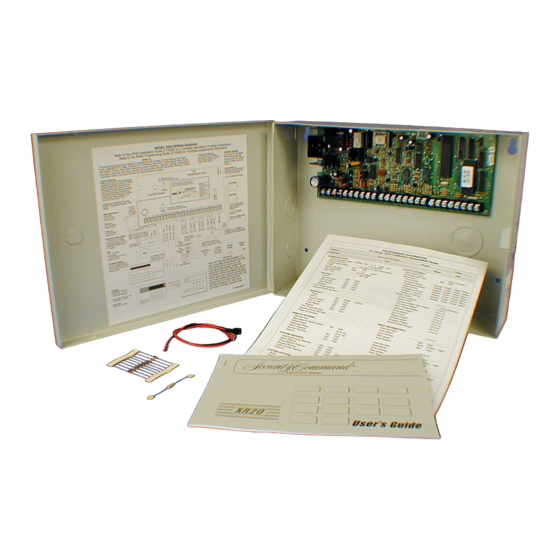
Command Processor Reset Phone Jack Connector BELL GND RED YEL GRN Z10+ Z10- Enclosure Mounting Holes Battery shelf Figure 2: XRSuper6/XR20/XR40 in standard 340 enclosure Accessory Module Accessory Module Mounting Holes Mounting Holes Dual 1/2" and 3/4" Conduit Knockouts T amper Switch... -
Page 10: Mounting Keypads
600mA. The transformer must be connected to a 120 VAC 60 Hz commercial power outlet that is not controlled by a wall switch. Never share the transformer output with any other equipment. XRSuper6/XR20/XR40 Installation Guide Digital Monitoring Products www.dmpnet.com... -
Page 11: Secondary Power Supply
Batteries supplied by DMP or manufactured by Eagle Picher or Yuasa have been tested to ensure proper charging with DMP products. GEL CELL BATTERIES CANNOT BE USED WITH THE XRSuper6/XR20/XR40 PANEL. 6.2 Earth ground Terminal 4 of the panel must be connected to earth ground using 14 gauge or larger wire to provide proper transient suppression. - Page 12 50mA ______ mA Active Zones 1-9 Qty _____ x 1.6mA ______ mA Qty _____ x *2mA ______ mA Active Zone 10 (zone 6 on XRSuper6) 4mA ______ mA 30mA ______ mA 2-Wire Smoke Detectors Qty _____ x .1mA ______ mA Qty _____ x .1mA ______ mA...
-
Page 13: Bell Output
Terminals 7, 8, 9, and 10 of the panel are designated as the keypad data bus. In addition to keypads, the XRSuper6/XR20/XR40 allows the connection of any combination of zone expanders, 5845LX Glassbreak Detectors, and 6155LX PIRs, to the data bus up to the maximum of four devices. The XRSuper6 allows the connection of four zones on address one. -
Page 14: Burglary Zones
The XR20/XR40 terminals 12 to 24 are the nine burglary zones. For programming purposes, the zone numbers are 1 to 9. The zone configurations on terminals 12 to 24 are described below. The XRSuper6 terminals 12 to 18 are the five burglary zones with terminal 16 providing the ground for zone 5. -
Page 15: Powered Zone For 2-Wire Smoke Detectors
A resettable 2-wire Class B powered zone is provided on terminals 25 (positive) and 26 (negative) of the panel. For programming purposes, the zone number is 10 on the XR20/XR40 and zone 6 on the XRSuper6. The zone uses a Model 309, 3.3k Ohm EOL resistor (provided with the panel) and has an operating range of 8.8 to 14.2 VDC. -
Page 16: Annunciator Outputs
The particular line(s) the service is connected to b. The FCC registration number c. The ringer equivalence d. The make, model, and serial number of the device XRSuper6/XR20/XR40 Installation Guide Digital Monitoring Products www.dmpnet.com 2500 N. Partnership Boulevard Springfield, MO 65803... -
Page 17: Ground Start
The digital dialer telephone number programmed for communication must not be a police station phone number, unless that phone number is specifically provided for that purpose. 15.4 Bypass reports The bypass reports option must be programmed as YES for all UL burglary applications. See the XRSuper6/XR20/ XR40 Programming Guide (LT-0305). 15.5 System maintenance Proper installation and regular maintenance by the installing alarm company and frequent testing by the end user is essential to ensure continuous satisfactory operation of any alarm system. - Page 18 A 12 VDC relay may be wired as a communication fail indicator. To install, connect the negative side of the indicator to one of the panel's annunciator outputs and the positive side to the smoke power (terminal 11 of the panel). See the XRSuper6/ XR20/XR40 Programming Guide (LT-0305).
- Page 19 Both programmed telephone numbers must begin with a D or P. See the XRSuper6/XR20/XR40 Programming Guide (LT-0305). 18.2 Entry delay The maximum entry delay used must not be more than 60 seconds. See the XRSuper6/XR20/XR40 Programming Guide (LT-0305). 18.3 Exit delay The maximum exit delay used must not be more than 60 seconds.
- Page 20 20.6 Fire zone programming Fire zones must be programmed to activate a trouble on open conditions and an alarm on short conditions. The swinger bypass function must not be used on any fire zones. See the XRSuper6/XR20/XR40 Programming Guide (LT-0305).
- Page 21 Troubleshooting CALIFORNIA STATE FIRE MARSHAL SPECIFICATIONS 22.1 Bell output definition The bell output of the Model XRSuper6/XR20/XR40 must be programmed to operate steady on burglary alarms and temporal on fire alarms. See the XRSuper6/XR20/XR40 Programming Guide (LT-0305). 23.1 Troubleshooting Section...
- Page 22 Installation 24.1 Multiple Indicating Circuit Module Installation XRSuper6/XR20/XR40 Installation Guide Digital Monitoring Products www.dmpnet.com 2500 N. Partnership Boulevard Springfield, MO 65803...
- Page 23 Installation 24.2 Installation for Derived Channel burglary XRSuper6/XR20/XR40 Installation Guide Digital Monitoring Products 2500 N. Partnership Boulevard Springfield, MO 65803 www.dmpnet.com...
- Page 24 Digital Monitoring Products 2500 N. Partnership Boulevard Springfield, MO 65803 800-641-4282...
Need help?
Do you have a question about the XRSuper6 and is the answer not in the manual?
Questions and answers