Calpeda NM Operating Instructions Manual
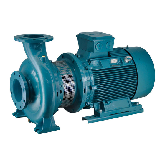
Close coupled centrifugal single-stage pumps, with flanged connections
Hide thumbs
Also See for NM:
- User manual ,
- Operating instructions manual (88 pages) ,
- Original operating instructions (48 pages)
Advertisement
Quick Links
Pompe centrifughe
monogiranti monoblocco,
con bocche flangiate
(grandezze EN 733)
NM
NM4
,
ISTRUZIONI ORIGINALI PER L'USO
1. Condizioni d'impiego
Esecuzione standard
- Per liquidi puliti senza parti abrasive, non
esplosivi, non aggressivi per i materiali della
pompa con temperatura massima di 90°C.
- Pressione finale massima ammessa nel
corpo pompa: 10 bar.
- Elettropompe previste per luoghi aerati e
protetti dalle intemperie con temperatura
massima ambiente di 40°C.
Potenza nominale motore
NM (2900 1/min) fino a kW:
2,2 7,5 30 75
NM4 (1450 1/min) fino a kW:
7,5 30 75
Pressione sonora dB (A) max:
70 80 85 90
Avviamenti/ora
max: 60 40 20 10
2. Installazione
Queste pompe sono previste per l'installazio-
ne con l'asse del rotore orizzontale e piedi di
appoggio in basso.
Installare la pompa il più vicino
possibile alla fonte di aspirazione.
3. Tubazioni
Il diametro interno delle tubazioni dipende
dalla portata desiderata.
Prevedere il diametro in modo che la velocità
del liquido non superi 1,5 m/s nell'aspirazio-
ne ed i 3 m/s nella mandata. In ogni caso il
diametro delle tubazioni non deve essere in-
feriore al diametro delle bocche della pompa.
Prima di collegare le tubazioni assicurarsi
della loro pulizia interna.
Ancorare le tubazioni su propri appoggi e col-
legarle in modo che non trasmettano forze,
tensioni e vibrazioni alla pompa.
La tubazione aspirante deve essere a
perfetta tenuta e deve avere un andamento
ascendente per evitare sacche d'aria.
Per il collegamento della bocca aspirante con
un tubo orizzontale di diametro superiore im-
piegare un raccordo eccentrico.
Per il funzionamento in aspirazione inseri-
re una valvola di fondo con succhie-
ruola che deve risultare sempre immersa.
Con l'aspirazione da serbatoio di prima raccol-
ta montare una valvola di non ritorno.
Con il funzionamento sotto battente inserire
una saracinesca.
Per aumentare la pressione della
rete di distribuzione osservare le
prescrizioni locali.
Nella tubazione di mandata in-
stallare una saracinesca per regolare portata,
prevalenza e potenza assorbita.
Installare un indicatore di pressione (mano-
metro).
Quando il dislivello geodetico in mandata è
maggiore di 15 m, tra pompa e saracinesca
inserire una valvola di ritegno per proteggere
la pompa da "colpi d'ariete".
4. Collegamento elettrico
Il collegamento elettrico deve es-
sere eseguito da un elettricista
qualificato nel rispetto delle pre-
scrizioni locali.
Seguire le norme di sicurezza.
Eseguire il collegamento a terra. Col-
legare il conduttore di protezione al morset-
tocontrassegnato con il simbolo
.
Confrontare la frequenza e la tensione di rete
con i dati di targa e collegare i conduttori di ali-
mentazione ai morsetti secondo il corri-
spondente schema riportato all'interno del
coperchio della scatola morsetti.
Con motori di potenza ≥ 5,5 kW
evitare l'avviamento diretto.
Prevedere un quadro con av-
viamento stella/triangolo o al-
tro dispositivo di avviamento.
ATTENZIONE: non fare mai cadere
una rondella o altre parti metalli-
che nel passaggio cavi interno tra
scatola morsetti e statore.
Se accade, smontare il motore e recupera-
re la parte caduta.
Italiano
Installare un dispositivo per la onnipolare
disinserzione dalla rete (interruttore per
scollegare la pompa dall'alimentazione) con
una distanza di apertura dei contatti di alme-
no 3 mm.
Con alimentazione trifase installare un ade-
guato salvamotore come da corrente di targa.
5. Avviamento
ATTENZIONE: evitare assolutamente
il funzionamento a secco, neanche
per prova. Avviare la pompa solo dopo
averla riempita completamente di liquido.
Con la pompa sopra il livello dell'acqua
da sollevare (funzionamento in aspirazione)
riempire il tubo aspirante e la pompa attraver-
so l'apposito foro.
Con il livello dell'acqua in aspirazione
sopra la pompa (funzionamento sotto bat-
tente) riempire la pompa aprendo lentamente
e completamente la saracinesca nel tubo
aspirante, tenendo aperta la saracinesca in
mandata per fare uscire l'aria.
Controllare che l'albero giri a mano.
Per questo scopo le elettropompe più piccole
hanno un intaglio per cacciavite sull'estremità
dell'albero lato ventilazione.
Verificare che il senso di rotazione
corrisponda a quello indicato dalla freccia sul
corpo pompa; in caso contrario togliere l'ali-
mentazione elettrica e invertire fra loro i colle-
gamenti di due fasi.
Avviare la pompa con la saracinesca in man-
data chiusa. Aprire poi lentamente la saraci-
nesca in mandata regolando il punto di fun-
zionamento entro i limiti indicati in targa.
Controllare che l'elettropompa lavori nel suo
campo di prestazioni e che non venga supe-
rata la corrente assorbita indicata in targa. In
caso contrario regolare la saracinesca, in
mandata o l'intervento di eventuali pressostati.
6. Manutenzione
La tenuta meccanica non richiede manuten-
zione.
Quando la pompa rimane inattiva, se esiste il
pericolo di gelo, deve essere svuotata com-
pletamente.
Prima di rimettere in marcia il motore control-
lare che l'albero non sia bloccato da incrosta-
zioni o altre cause e riempire completamente
di liquido il corpo pompa.
Prima di ogni intervento di
manutenzione togliere l'ali-
mentazione elettrica. (Solo la
regolazione del premitreccia, cap. 7. e la lu-
brificazione, cap. 8., possono essere esegui-
te, con precauzione, con il motore in moto).
7. Pompe con tenuta a treccia
Al primo avviamento allentare leggermente il
premitreccia in modo che la guarnizione ven-
ga decompressa.
Successivamente regolare il premitreccia fi-
no ad ottenere il normale gocciolamento in-
dice di una regolare lubrificazione della tenuta.
La guarnizione a treccia deve essere sosti-
tuita quando le sue proprietà di tenuta sono
sensibilmente diminuite.
Un pacco troppo compresso, indurito e sec-
co causa l'usura dell'albero.
8. Lubrificazione cuscinetti
Fino alla grandezza 160 i motori hanno cusci-
netti a lubrificazione permanente e non richie-
dono alcuna rilubrificazione.
Dalla grandezza 180 i motori sono dotati di
ingrassatori. Una rilubrificazione ad intervalli
regolari (circa 5000 h) è raccomandata solo
per condizioni di funzionamento molto gravo-
se, con alte temperature ambiente. Un ecces-
so di grasso è dannoso. Usare grasso a base
di litio per alte temperature.
9. Smontaggio
Prima dello smontaggio chiudere le saracine-
sche in aspirazione e mandata e svuotare il
corpo pompa.
Per lo smontaggio ed il rimontaggio osserva-
re la costruzione sul disegno in sezione.
Con i piedi sotto il corpo pompa, togliendo i
dadi (14.28), si estrae il motore completo con
la girante senza rimuovere il corpo pompa
dalla tubazione.
10. Ricambi
Nelle eventuali richieste di parti di ricambio
precisare il numero di posizione nel disegno
in sezione ed i dati di targa.
Impiegare cuscinetti con gioco C3 e grasso
per elevate temperature.
Eventuali pompe da ispezionare
o riparare prima della spedizione
o messa a disposizione devono
essere svuotate e accuratamente
pulite internamente ed esterna-
mente.
Con riserva di modifiche.
Close coupled centrifugal
single-stage pumps,
with flanged connections
(sizes EN 733)
NM
NM4
,
ORIGINAL OPERATING INSTRUCTIONS
1. Operating conditions
Standard construction
- For clean liquids without abrasives, non-
explosive, non-aggressive for the pump
materials, with a maximum temperature of
90 °C.
- Maximum permissible working pressure up
to 10 bar.
- Installation in well ventilated location pro-
tected from the weather, with a maximum
ambient temperature of 40 °C;.
Rated motor power
NM (2900 1/min) up to kW:
2,2 7,5 30 75
NM4 (1450 1/min) up to kW:
7,5 30 75
Sound pressure dB (A)
max: 70 80 85 90
Starts per hour
max: 60 40 20 10
2. Installation
These pumps must be installed with the rotor
axis horizontal and feet downwards.
Place the pump as close as possible to the
suction source.
3. Pipes
The inside diameter of the pipe-work de-
pends on the desired flow.
Provide a diameter assuring a liquid flow not
greater than 1.5 m/s for suction and 3 m/s for
delivery.
The pipe diameters must never be smaller
than the pump connections.
Ensure the inside of pipes are clean before
connection.
Secure all pipes to rests and connect them
so that they are not under stress, and do not
transmit vibration or flexing strain to the
pump.
The suction pipe must be perfectly airtight
and be led upwards in order to avoid air
pockets.
Use an eccentric transition piece to join the
suction connection with a horizontal pipe of
larger diameter.
For suction lift operation fit a foot valve
with strainer which must always remain
immersed.
For suction from a storage tank fit a check
valve.
For positive suction head operation fit a gate
valve.
Follow local specifications if increasing
network pressure.
Fit a gate valve into the delivery pipe to
adjust delivery, head, and absorbed power.
Install a pressure gauge.
With a geodetic head outlet over 15 m fit a
check valve between the pump and the gate
valve in order to protect the pump from water
hammering.
4. Electrical connection
Electrical connection must be
carried out only by a qualified
electrician and in accordance with
local regulations.
Follow all safety standards.
The unit must be properly earthed
(grounded).
Connect the earthing (grounding) conduc-
tor to the terminal with the
marking.
Compare the frequency and mains voltage
with the name-plate data and connect the
supply conductors to the terminals in accor-
dance with the appropriate diagram inside
the terminal box cover.
With motor power rating ≥ 5,5 kW,
avoid direct starting.
Provide a control panel with star-
delta starting or an other starting
device.
ATTENTION: never allow washers
or other metal parts to fall into the
internal cable opening between the
terminal box and stator.
If this occurs, dismantle the motor to reco-
ver the object which has fallen inside.
English
Install a device for disconnection
from the mains (switch) with a contact sepa-
ration of at least 3 mm on all poles.
With three-phase motor provide an over-
load-protection device in line with the name-
plate current.
5. Starting
ATTENTION: never run the pump
dry - not even for a short trial run.
Start the pump after filling it completely
with liquid.
When the pump is located above
the water level (suction lift operation) fill
the suction pipe and the pump through the
priming hole.
When the liquid level on the suction
side is above the pump (inflow under
positive suction head), fill the pump by ope-
ning the suction gate valve slowly and com-
pletely, keeping the delivery gate valve open
to release the air.
Check that the shaft turns by hand.
For this purpose the smaller pumps have a
screwdriver notch on the ventilation side of the
shaft end.
Check that the direction of rotation
is as shown by the arrow on the pump ca-
sing, otherwise disconnect electrical power
and reverse the connections of two phases.
Switch on the pump with the delivery gate
valve closed.
Slowly open the discharge valve to obtain
the required pump duty point within the field
of performance shown on the name-plate.
Check that the pump works within
its field of performance, and that
the absorbed current shown on the
name-plate is not exceeded.
Otherwise adjust the delivery gate
valve or the setting of any pressure switches.
6. Maintenance
The mechanical seal does not require any
maintenance.
When the pump is not used, empty it com-
pletely if freezing may be expected.
Before restarting the unit, check that the
shaft is not jammed and fill the pump casing
completely with liquid.
Disconnect electrical power
before any servicing operation.
(Only adjustment of the stuffing
box, section 7., and lubrication
procedure, section 8., may be performed, with
caution, while motor is running).
7. Pumps with packing seal
First loosen the gland slightly so that the
seal is decompressed. Then adjust the
gland, leaving a regular leakage-drip, which
indicates proper lubrification.
The packed gland must be repla-
ced when its sealing properties ha-
ve considerably decreased. A
compressed, hardened and dry
packing causes the shaft to wear.
8. Bearings lubrication
Up to frame size 160 the motors have prelu-
bricated bearings and they do not require any
relubrication.
From frame size 180 the motors have grease
nipples. A relubrication at regular intervals
(about 5000 h) is recommended only in heavy
working conditions, with high ambient tempe-
ratures. An excess of grease is harmful. Use
lithium base grease for high temperatures.
9. Dismantling
Close the suction and delivery gate valves
and drain the pump casing before disman-
tling the pump.
For dismantling and re-assembly see con-
struction in the cross section drawing.
With the feet under the pump casing (back
pull-out design), by removing the nuts
(14.28) the motor can be removed complete
with impeller, without removing the pump
casing and pipe-work.
10. Spare parts
When ordering spare parts, please quote
data stamped on the name-plate
and the position number of each
spare part required in accordance
with the cross section drawing.
Use bearings with C3 clearance
and grease for high temperatures.
Any pumps that require inspec-
tion/repair must be drained and
carefully cleaned inside and out-
side before dispatch/submission.
Changes reserved.
Advertisement

Subscribe to Our Youtube Channel
Related Manuals for Calpeda NM


Summary of Contents for Calpeda NM
- Page 1 40 °C;. Potenza nominale motore Controllare che l’albero giri a mano. For this purpose the smaller pumps have a NM (2900 1/min) fino a kW: 2,2 7,5 30 75 Rated motor power Per questo scopo le elettropompe più piccole...
- Page 2 Contrôler que l’arbre tourne à la main. A Motornennleistung öffnen, damit die Luft entweichen kann. cet effet les pompes plus petites ont une NM (2900 1/min) bis kW: 2,2 7,5 30 75 Puissance nominale moteur Nachprüfen, ob sich die Welle von Hand rainure pour tournevis sur l’extémité...
- Page 3 Potencia nominal motor Controlar que el eje gira con la mano. ningstemperatur av 40 °C. sidan för att avlägsna luftansamlingar. NM (2900 1/min) hasta a kW: 2,2 7,5 30 75 Con este fin las electrobombas más pequeñas Motoreffekt Kontrollera att pumpaxeln roterar för hand,...
- Page 4 Motorvermogen: ÅëÝãîôå üôé ç ðåñéóôñïöÞ ôïõ ñüôïñá åßíáé inkeping aan de ventilatorzijde van de as. NM (2900 1/min) tot 2,2 7,5 30 75 NM (29001/min) ìÝ÷ñé óå kW: 2,2 7,5 30 75 üðùò äåß÷íåé ôï âÝëïò óôï óþìá ôçò áíôëßáò, åéäÜëëùò...
- Page 5 82.08 90.00 14.28 90°C. 70.20 98.00 76.54 94.00 82.00 - 10 28.00 40°C. NM (2900 2,2 7,5 30 75 NM4 (1450 7,5 30 75 . 70 80 85 90 . 60 40 20 10 4.93.320 28.04 28.20 14.20 36.00 73.00 76.00...
- Page 6 DICHIARAZIONE DI CONFORMITÀ Noi CALPEDA S.p.A. dichiariamo sotto la nostra esclusiva responsabilità che le Pompe NM, B-NM, I-NM, NM4, B-NM4, I-NM4, tipo e numero di serie riportati in targa, sono conformi a quanto prescritto dalle Direttive 2004/108/CE, 2006/42/CE, 2006/95/CE e dalle relative norme armonizzate.
Need help?
Do you have a question about the NM and is the answer not in the manual?
Questions and answers