Table of Contents
Advertisement
Quick Links
Advertisement
Chapters
Table of Contents

Related Manuals for Beckhoff KL6771 Series


Summary of Contents for Beckhoff KL6771 Series
- Page 1 Documentation KL6771 MP-Bus Master Terminals Version: 2.0.0 Date: 2018-01-16...
-
Page 3: Table Of Contents
Table of contents Table of contents 1 Foreword .............................. 5 Notes on the documentation...................... 5 Safety instructions .......................... 6 Documentation Issue Status...................... 7 2 Product overview............................ 8 Introduction ............................. 8 Basic Function Principles........................ 9 Diagnostic LEDs ........................... 10 Technical Data.......................... 11 3 Mounting and wiring .......................... 12 Installation on mounting rails ...................... - Page 4 Table of contents Version: 2.0.0 KL6771...
-
Page 5: Foreword
The TwinCAT Technology is covered, including but not limited to the following patent applications and patents: EP0851348, US6167425 with corresponding applications or registrations in various other countries. ® EtherCAT is registered trademark and patented technology, licensed by Beckhoff Automation GmbH, Germany Copyright © Beckhoff Automation GmbH & Co. KG, Germany. -
Page 6: Safety Instructions
All the components are supplied in particular hardware and software configurations appropriate for the application. Modifications to hardware or software configurations other than those described in the documentation are not permitted, and nullify the liability of Beckhoff Automation GmbH & Co. KG. Personnel qualification This description is only intended for trained specialists in control, automation and drive engineering who are familiar with the applicable national standards. -
Page 7: Documentation Issue Status
From firmware version B3, the MP-bus master terminal can also be used in cablings with 24 V • TwinCAT libraries chapter revised. 1.2.0 • Programming description moved to the Beckhoff Information System [} 25] • TwinCAT library TcMPBus (formerly TcKL6771) updated to version 1.8.0 • ATEX notes added 1.1.0 •... -
Page 8: Product Overview
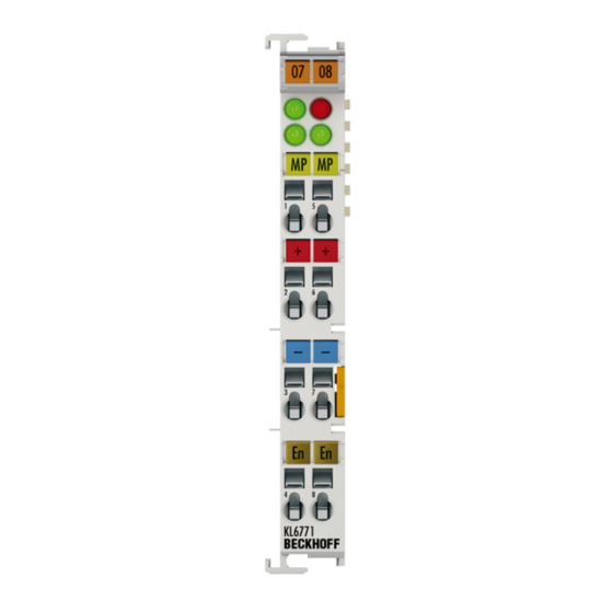
Product overview Product overview Introduction Fig. 1: KL6771 The MP-bus master terminal enables direct connection of MP-bus slaves. The MP-Bus was developed by Belimo for connecting valves, throttle valves, air valves, fire dampers, and for window ventilation systems. Up to 16 field devices, 8 drives and 8 sensors can be connected to the KL6771. Process data exchange is fieldbus-independent. -
Page 9: Basic Function Principles
Product overview Basic Function Principles Fig. 2: Basic Function Principles Operation of the MP-bus Bus Terminal requires function blocks that are available for download [} 25]. The following drives and sensors are supported: • VAVs (e.g. NMV-D2M) • FLS window opener • Flap and positioning actuators (e.g. NM24-MFT2, NV23-MFT2) •... -
Page 10: Diagnostic Leds
Product overview Diagnostic LEDs The LEDs indicate the operating state of the KL6771. Fig. 3: LEDs Meaning of the LED displays Color Chan- State and significance flashes K-Bus Run green 1 Lit, either weakly or strongly: K-bus No K-Bus K-Bus communication communication OK communication MP-Bus Error red... -
Page 11: Technical Data
Product overview Technical Data Technical Data KL6771-0000, KS6771-0000 Master channels Transmission standard MP-bus standard Number of slaves max. 16 (8 actuators and 8 sensors) Data transfer rate 1200 baud Electrical isolation 500 V (K-bus / MP-bus) Power supply for the electronics via the K-bus and through the power contacts Current consumption from the K-bus typically 55 mA Current consumption from power... -
Page 12: Mounting And Wiring
Mounting and wiring Mounting and wiring Installation on mounting rails Risk of electric shock and damage of device! Bring the bus terminal system into a safe, powered down state before starting installation, disassembly or wiring of the Bus Terminals! WARNING Assembly Fig. 4: Attaching on mounting rail The Bus Coupler and Bus Terminals are attached to commercially available 35 mm mounting rails (DIN rails... -
Page 13: Fig. 5 Disassembling Of Terminal
Mounting and wiring Disassembly Fig. 5: Disassembling of terminal Each terminal is secured by a lock on the mounting rail, which must be released for disassembly: 1. Pull the terminal by its orange-colored lugs approximately 1 cm away from the mounting rail. In doing so for this terminal the mounting rail lock is released automatically and you can pull the terminal out of the bus terminal block easily without excessive force. -
Page 14: Installation Instructions For Enhanced Mechanical Load Capacity
Mounting and wiring Fig. 6: Power contact on left side Possible damage of the device Note that, for reasons of electromagnetic compatibility, the PE contacts are capacitatively coupled to the mounting rail. This may lead to incorrect results during insulation testing or Attention to damage on the terminal (e.g. -
Page 15: Connection
Mounting and wiring Additional installation instructions For terminals with enhanced mechanical load capacity, the following additional installation instructions apply: • The enhanced mechanical load capacity is valid for all permissible installation positions • Use a mounting rail according to EN 60715 TH35-15 •... -
Page 16: Fig. 8 Pluggable Wiring
Mounting and wiring Pluggable wiring (ESxxxx / KSxxxx) Fig. 8: Pluggable wiring The terminals of ESxxxx and KSxxxx series feature a pluggable connection level. The assembly and wiring procedure is the same as for the ELxxxx and KLxxxx series. The pluggable connection level enables the complete wiring to be removed as a plug connector from the top of the housing for servicing. -
Page 17: Wiring
Mounting and wiring 3.3.2 Wiring Risk of electric shock and damage of device! Bring the bus terminal system into a safe, powered down state before starting installation, disassembly or wiring of the Bus Terminals! WARNING Terminals for standard wiring ELxxxx/KLxxxx and for pluggable wiring ESxxxx/KSxxxx Fig. 10: Connecting a cable on a terminal point Up to eight terminal points enable the connection of solid or finely stranded cables to the Bus Terminal. - Page 18 Mounting and wiring Terminal housing High Density Housing Wire size width (single core wires) 0.08 ... 1.5 mm Wire size width (fine-wire conductors) 0.25 ... 1.5 mm Wire size width (conductors with a wire end sleeve) 0.14 ... 0.75 mm Wire size width (ultrasonically “bonded" conductors) only 1.5 mm Wire stripping length 8 ...
-
Page 19: Connection
Mounting and wiring Connection Risk of injury through electric shock and damage to the device! Bring the Bus Terminals system into a safe, de-energized state before starting mounting, disassembly or wiring of the Bus Terminals! WARNING Fig. 11: Connection Terminal point Connection for MP-Bus Cable 5 (white or orange) -
Page 20: Mp-Bus Cabling
Mounting and wiring MP-Bus cabling Risk of injury through electric shock and damage to the device! Bring the Bus Terminals system into a safe, de-energized state before starting mounting, disassembly or wiring of the Bus Terminals! WARNING Maximum MP-bus length The maximum cable length is obtained by considering the following points: •... -
Page 21: Fig. 14 Mp-Bus Length In Relation To The Effective Power Of All Drives
Mounting and wiring MP-Bus length in relation to the effective power of all drives Fig. 14: MP-Bus length in relation to the effective power of all drives Example with 4 drives = 1.3 W + 2.5 W + 6.0 W + 3.0 W = 12.8 W total Wire cross-section in mm²... -
Page 22: Atex - Special Conditions (Standard Temperature Range)
• EN 60079-0:2012+A11:2013 • EN 60079-15:2010 Marking The Beckhoff fieldbus components with standard temperature range certified for potentially explosive areas bear one of the following markings: II 3G KEMA 10ATEX0075 X Ex nA IIC T4 Gc Ta: 0 … 55°C II 3G KEMA 10ATEX0075 X Ex nC IIC T4 Gc Ta: 0 … 55°C Version: 2.0.0... -
Page 23: Atex Documentation
Notes about operation of the Beckhoff terminal systems in potentially explo- sive areas (ATEX) Pay also attention to the continuative documentation Note Notes about operation of the Beckhoff terminal systems in potentially explosive areas (ATEX) that is available in the download area of the Beckhoff homepage http:\\www.beckhoff.com! KL6771... -
Page 24: Mp-Bus
MP-Bus MP-Bus Introduction MP-bus = multi-point bus The MP-Bus (Multi-Point) is a simple sensor/actuator bus, which is used for certain sub-systems of the building automation system. The MP-Bus serves to control HVAC actuators for flaps, control valves and volume flow regulators from the Belimo product range. Up to eight different devices from HVAC systems can be connected to an MP-Bus master using 3-wire technology. -
Page 25: Programming
Programming Programming TwinCAT libraries Software documentation in the Beckhoff Information System: TwinCAT 2: TwinCAT 2 PLC Lib: MP-Bus TwinCAT 3: TwinCAT 3 PLC Lib: Tc2_MPBus KL6771 Version: 2.0.0... -
Page 26: Appendix
Beckhoff's branch offices and representatives Please contact your Beckhoff branch office or representative for local support and service on Beckhoff products! The addresses of Beckhoff's branch offices and representatives round the world can be found on her internet pages: http://www.beckhoff.com You will also find further documentation for Beckhoff components there. - Page 27 List of illustrations List of illustrations Fig. 1 KL6771 ............................Fig. 2 Basic Function Principles......................Fig. 3 LEDs ............................Fig. 4 Attaching on mounting rail ......................Fig. 5 Disassembling of terminal......................Fig. 6 Power contact on left side......................Fig. 7 Standard wiring..........................
Need help?
Do you have a question about the KL6771 Series and is the answer not in the manual?
Questions and answers