Sign In
Upload
Manuals
Brands
DMP Electronics Manuals
Control Panel
XR200
DMP Electronics XR200 Manuals
Manuals and User Guides for DMP Electronics XR200. We have
2
DMP Electronics XR200 manuals available for free PDF download: Programming Manual, Installation Manual
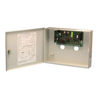
DMP Electronics XR200 Programming Manual (56 pages)
Command Processor and Addressable Fire alarm system control panel
Brand:
DMP Electronics
| Category:
Control Panel
| Size: 1 MB
Table of Contents
Programming Guide
2
Table of Contents
3
Revisions to this Document
8
Before You Begin
9
Getting Started
9
Programmer Lockout Codes
10
Programmer Operation
10
Entering Alpha Characters
11
Reset Timeout
11
Special Keys
11
Entering Non-Alpha Characters
12
Keypad Prompts Display Current Programming
12
Initialization
13
Clear All Memory
13
Clear All Codes
13
Clear All Schedules
13
Clear Display Events Memory
13
Clear Zone Information
13
Clear Area Information
13
Clear Output Information
13
Clear Communication and Remote Options
13
Set to Factory Defaults
13
Communication 3.1 Communication
14
Communication Type
14
Retry Time
14
Host Backup
15
Modem Setup
15
Ul Aa
16
2ND Phone Line
17
Test Frequency
18
Account Number
18
Transmit Delay
18
Dtmf
18
Events Manager
18
Defer Test Time
19
Test Frequency
19
Test Time
19
Receiver One Programming
20
Alarm Reports
20
Supervisory/Trouble Reports
20
Opening/Closing and User Reports
20
Test Report
20
Backup Reporting
20
First Telephone Number
20
Second Telephone Number
20
Receiver One Programming
21
Pager Type
21
Alarm Reports
21
Supervisory/Trouble Reports
21
Opening/Closing and User Reports
21
Test Report
21
Backup Reporting
21
First Telephone Number
21
Second Telephone Number
21
Pager Identification Number
21
Device Setup
22
Maximum Partitions
22
Device Type
22
Partition Number
22
Remote Options
23
Remote Key
23
Manufacturer Authorization
23
Armed Rings
23
Disarmed Rings
23
Alarm Receiver Authorization
23
Service Receiver Authorization
24
Remote Phone Number
24
Remote Disarm
24
System Reports
25
Abort Report
25
Restoral Reports
25
Bypass Reports
25
Schedule Change Reports
25
Code Change Reports
25
Access Keypads
25
Ambush
25
System Options 7.1 System Options
26
Closing Wait
26
Entry Delay 1
26
Cross Zone Time
26
Zone Retard Delay
26
Power Fail Delay
26
Swinger Bypass Trips
26
Reset Swinger Bypass
26
Video/Alarm Verification
27
Time Zone Changes
27
AC Cycles
27
Output Options
28
Communication Fail Output
29
Menu Display
30
Status List
31
Burglary Zones
32
Printer Reports
33
Host Log Reports
34
Modem Setup
34
Arm and Disarm Reports
34
Zone Reports
34
User Command Reports
34
Door Access Reports
34
Supervisory Reports
34
Area Information 13.1 Area Information
35
Partition Number
35
Arming Mode
35
Exit Delay
35
Burglary Bell Output
35
Opening/Closing Reports
36
Closing Check
36
Closing Code
36
Any Bypass
36
Area Schedules
36
Primary/Secondary Schedules
36
Area Number
36
Area Name
37
Account Number
37
Automatic Arming
37
Bad Zones
37
Automatic Disarming
37
Armed Output Number
38
Common Area
38
Zone Information 14.1 Zone Information
39
Zone Number
39
Zone Name
39
Zone Type
39
Fire Bell Output
40
Partition Number
40
Area Number
40
Area Assignment
40
Arming Zone Area Assignment
40
Style
41
Next Zone
41
Wireless
42
Check-In Time
42
Internal Contact
42
End-Of-Line
42
Normally Open
42
Alarm Action
42
Disarmed Open
42
Report to Transmit
43
Output Number
43
Output Action
43
Swinger Bypass
44
Prewarn Addresses
44
Entry Delay
44
Zone Retard
44
Presignal Addresses
44
Fast Response
44
Cross Zone
45
Priority
45
Program Transmitter
45
Connect Transmitter
45
Connect Command Transmitter
45
Set Lockout Code
46
Stop
46
17 - Appendix
47
17.1 Diagnostics Function
47
17.2 Using the 984 Command Function
48
17.3 Using the Walk Test
49
Walk Test
49
Zone Types
49
Bell Action
49
Trip Counter
49
Failed Zones Display
50
Local Printer for Walk Test
50
690 Series Keypads Speaker Operation
50
17.5 Pager Direct Specifications
50
17.6 Cross Zoning
51
17.7 Events Manager
51
17.8 Modem Setup Information
51
17.9 Host Backup Examples
52
462N Network Interface Card Examples
53
Zone Type Descriptions
54
Zone Type Specifications
55
Common Keypad Messages
56
Advertisement
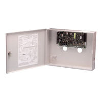
DMP Electronics XR200 Installation Manual (32 pages)
242-ZONE PANEL
Brand:
DMP Electronics
| Category:
Control Panel
| Size: 1 MB
Table of Contents
Table of Contents
3
Revisions to this Document
6
Product Specifications
7
Power Supply
7
Communication
7
Panel Zones
7
Keypad Data Bus
7
LX-Bus
7
Outputs
7
Enclosure Specifications
7
Panel Features
8
Description
8
Expansion Zones
8
Relay Output Expansion
8
Partitions and Areas
9
Central Station Communication
9
Before You Begin
9
About this Guide
9
How to Use this Guide
9
System Components
10
Description
10
Wiring Diagram
10
Lightning Protection
11
Accessory Devices
11
Installation
12
Mounting the Enclosure
12
Mounting Keypads and Zone Expansion Modules
13
Connecting Serial Devices
13
Primary Power Supply
13
AC Terminals 1 and 2
13
Transformer Types
13
Secondary Power Supply
14
Battery Terminals 3 and 4
14
Earth Ground
14
Battery Only Restart
14
Replacement Period
14
Discharge/Recharge
14
Battery Supervision
14
Battery Cutoff
14
XR200 Power Requirements
14
Bell Output
16
Terminals 5 and 6
16
Keypad Data Bus 8.1 Description
16
Terminal 7 - RED
16
Terminal 8 - YELLOW
16
Terminal 9 - GREEN
16
Terminal 10 - BLACK
16
Smoke and Glassbreak Detector Output
16
Terminals 11 and 12
16
Current Rating
16
Protection Zones
17
Terminals 13-24
17
Operational Parameters
17
Zone Response Time
17
Keyswitch Arming Zone
17
Powered Zones for 2-Wire Smoke Detectors
17
Terminals 25-26 and 27-28
17
Zone Information
17
Compatible 2-Wire Smoke Detector Chart
18
Dry Contact Relay Outputs
19
Description
19
Contact Rating
19
Output Harness Wiring
19
VDC Voltage Outputs 3 to
19
Telephone RJ Connector
20
Description
20
FCC Registration
20
Notification
20
Ground Start
20
Answering Machine Bypass
20
Reset and Tamper Headers
21
J16 Reset Header
21
J4 Tamper Header
21
Universal UL and NFPA Fire Alarm Specifications
22
Introduction
22
Wiring
22
Transformer
22
End-Of-Line Resistor
22
System Trouble Display
22
Fire Display
22
Police Station Phone Number
22
System Maintenance
22
Audible Alarm
22
UL 985 NFPA 72 (Chapter 2) Specifications
23
Bell Output Definition
23
UL 864 NFPA 72 (Chapter 9) Specifications
23
Zone Restoral Reports
23
Power Fail Delay
23
Sprinkler Supervisory
23
DACT Systems
23
Type 2 and Type 3 Central Station Service
23
Type 1 Central Station Service
23
Local Protective Signaling Systems
24
Proprietary Protective Signaling Systems
24
Remote Station Protective Signaling Systems
24
Fire Protective Signaling Systems with an Icom
24
California State Fire Marshal Specifications
24
Bell Output Definition
24
Wiring Diagrams
25
Notification Circuit Module Installation
25
Multiple Notification Circuit Module Installation
26
Multiple Notification Circuit Modules for Zoned Annunciation
27
Dual Style D Zone Module Installation
28
Remote Station Reversing Relay Connection
29
Supervised Remote Relay Connection
30
LX-Bus Module Connection
31
Operating Instructions
32
Advertisement
Related Products
DMP Electronics Addressable Fire Alarm Control Panel XR2500F
DMP Electronics Security Command XR20
DMP Electronics XR2400F
DMP Electronics XR500N SERIES
DMP Electronics XRSuper6
DMP Electronics XR40
DMP Electronics XR550INT Series
DMP Electronics XR150CAN Series
DMP Electronics XR150FC Series
DMP Electronics COMMAND PROCESSOR XR100N
DMP Electronics Categories
Control Unit
Keypad
Control Panel
Transmitter
Security Sensors
More DMP Electronics Manuals
Login
Sign In
OR
Sign in with Facebook
Sign in with Google
Upload manual
Upload from disk
Upload from URL