Table of Contents
Advertisement
Quick Links
Advertisement
Table of Contents

Related Manuals for Advantech PCI-1784U


Summary of Contents for Advantech PCI-1784U
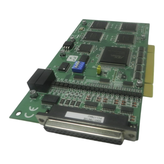
- Page 1 PCI-1784U 4-Axis Quadrature Encoder & Counter Card User Manual...
- Page 2 No part of this man- ual may be reproduced, copied, translated or transmitted in any form or by any means without the prior written permission of Advantech Co., Ltd. Information provided in this manual is intended to be accurate and reli- able.
- Page 3 Product Warranty (2 years) Advantech warrants to you, the original purchaser, that each of its prod- ucts will be free from defects in materials and workmanship for two years from the date of purchase. This warranty does not apply to any products which have been repaired or...
- Page 4 This product has passed the CE test for environmental specifications when shielded cables are used for external wiring. We recommend the use of shielded cables. This kind of cable is available from Advantech. Please contact your local supplier for ordering information.
- Page 5 National Fire Protection Association, work sites are classified into differ- ent classes, divisions and groups, based on hazard considerations. PCI-1784U is compliant with the specifications of Class I, Division 2, Groups A, B, C and D indoor hazards. Technical Support and Assistance Step 1.
- Page 6 The sound pressure level at the operator's position according to IEC 704- 1:1982 is no more than 70 dB (A). DISCLAIMER: This set of instructions is given according to IEC 704-1. Advantech disclaims all responsibility for the accuracy of any statements contained herein. PCI-1784U User Manual...
- Page 7 Safety Precaution - Static Electricity Follow these simple precautions to protect yourself from harm and the products from damage. To avoid electrical shock, always disconnect the power from your PC chassis before you work on it. Don't touch any components on the CPU card or other cards while the PC is on.
- Page 8 PCI-1784U User Manual viii...
-
Page 9: Table Of Contents
Contents Chapter 1 Introduction ............. 2 Features ................2 Applications ..............4 Installation Guide ............. 5 Figure 1.1:Installation Flow Chart ......... 6 Software Overview ............7 Device Driver Programming ..........8 Accessories ..............10 Chapter 2 Installation ............. 12 Unpacking ..............12 Driver Installation ............ - Page 10 Table C.16:Register for Reset counter ......50 Appendix D Operation ............52 Quadrature Encoder Introduction ........52 Counter Modes ............... 53 Digital Noise Filter ............54 Latch Mode ..............55 Counter Reset Value ............56 Timer Function..............56 Interrupt Function ............57 PCI-1784U User Manual...
- Page 11 Introduction Sections include: • Features • Applications • Installation Guide • Software Overview • Device Driver Programming • Accessories...
-
Page 12: Chapter 1 Introduction
Chapter 1 Introduction Thank you for buying the Advantech PCI-1784U. The PCI-1784U is a 4- axis quadrature encoder and counter card for PCI bus. This card includes four 32-bit quadruple AB phase encoder counters, 8-bit timer with multi range time-base selector, four isolated digital inputs, and four isolated digital outputs. - Page 13 Quadrature input works with or without an index, allowing linear or rotary encoder feedback. Counters The PCI-1784U has four independent 32-bit counters. The maximum quadrature input rate is 2 MHz, and the maximum input rate in counter mode is 8 MHz. You can individually configure each counter for quadra- ture decoding, pulse/direction counting or up/down counting.
-
Page 14: Applications
Keeping the Counter Values & Output Status after System Reset Users can independently use the four counter channels. When the system is hot reset (power not shut down), the PCI-1784U can either retain the last counter values and the output status, or return to its default configura- tion, depending on the jumper setting. -
Page 15: Installation Guide
1.3 Installation Guide Before you install your PCI-1784U card, please make sure you have the following necessary components: PCI-1784U DA&C card PCI-1784U User’s Manual Driver software Advantech DLL drivers (In the CD-ROM) Wiring cable PCL-10137H (option) Wiring board ADAM-3937 (option) - Page 16 Install Driver from CD-ROM, then power-off PC Install Hardware and power-on PC Use driver utility to configure hardware Use test utility to test hardware Read examples & driver manual Start to write your own application Figure 1.1: Installation Flow Chart PCI-1784U User Manual...
-
Page 17: Software Overview
Device Drivers The Advantech Device Drivers software is included on the companion CD-ROM at no extra charge. It also comes with all the Advantech DA&C cards. Advantech’s device drivers feature a complete I/O function library to help boost your application performance. The Advantech Device Driv- ers for Windows 2000/XP works seamlessly with development tools such as Visual C++, Visual Basic, Inprise C++ Builder and Inprise Delphi. -
Page 18: Device Driver Programming
• C++ Builder For instructions on how to begin programming works in each develop- ment tool, Advantech offers a Tutorial Chapter in the Device Drivers Manual for your reference. Please refer to the corresponding sections in this chapter on the Device Drivers Manual to begin your programming efforts. - Page 19 Drivers Manual. Programming with Device Drivers Function Library Advantech Device Drivers offers a rich function library to be utilized in various application programs. This function library consists of numerous APIs that support many development tools, such as Visual C++, Visual Basic, Delphi and C++ Builder.
-
Page 20: Accessories
Wiring Cable PCL-10137H The PCL-10137H shielded cable is specially designed for PCI-1784U cards to provide high resistance to noise. To achieve a better signal quality, the signal wires are twisted in such a way as to form a “twisted-pair cable,” reducing cross talk and noise from other signal sources. - Page 21 Installation Sections include: • Unpacking • Driver Installation • Hardware Installation...
-
Page 22: Chapter 2 Installation
This chapter gives users an item checklist, proper instructions on unpack- ing, and step-by-step procedures for driver and card installation. 2.1 Unpacking After receiving your PCI-1784U package, please inspect its contents first. The package should contain the following items: • PCI-1784U card •... -
Page 23: Driver Installation
PC or transport it elsewhere. 2.2 Driver Installation We recommend you to install the driver before you install the PCI-1784U card into your system, since this will guarantee a smooth installation pro- cess. - Page 24 Step 3: Please click ‘CONTINUE’ to proceed to the next step. Step 4: Please select ‘Installation’ to proceed to the next step. A list of items will be shown on the screen: ‘Device Manager’, ’Individual Driver’, ‘Example & Utility’, and ‘Advance Options’. PCI-1784U User Manual...
- Page 25 Step 5: Please install the ‘Device Manager’ first. For details on how to install the ‘Device Manager’ step by step, please see the software manual. Step 6: When you’re finished installing the ‘Device manager’, you can install the driver of the corresponding card. Please click the ‘Individual Drivers’...
- Page 26 Step 7: Select ‘PCI Series’. Step 8: Select ‘PCI-1784’ to install its driver. For more information about the software installation, please read the software manual. PCI-1784U User Manual...
-
Page 27: Hardware Installation
Step 4: Touch the metal part on the surface of your computer to neutralize the static electricity that might be on your body. Step 5: Insert the PCI-1784U card into a PCI slot. Hold the card by its edges and carefully align with the slot. Insert the card firmly into place. - Page 28 After the PCI-1784U card is installed, you can verify whether it is prop- erly installed on your system in the Device Manager: The device name of the PCI-1784 should be listed on the Device Manager tab on the System Property Page.
-
Page 29: Device Setup & Configuration
The Device Manager program is a utility that allows you to set up, con- figure and test your device, and later stores your settings on the system registry. These settings will be used when you call the APIs of Advantech Device Drivers. - Page 30 Item 7: Set timer counter (count 4) timer divider and timer base clock. Item 8: Set DO mode. Item 9: Set digital filter clock. Item 10: Default setting restore counter setting to default, Current Setting return the device current hardware settings. PCI-1784U User Manual...
- Page 31 Signal Connections Sections include: • Overview • Switch & Jumper Settings • Signal Connections...
-
Page 32: Chapter 3 Signal Connections
PCI- 1784U via the I/O connector. 3.2 Switch & Jumper Settings The PCI-1784U card has one function switch and five jumper settings. Figure 3.1: Card Connectors, Jumpers & Switches Table 3.1: Summary of Jumper Settings... - Page 33 Complete loss of power to the chip clears the chip memory. Thus, no mat- ter how JP2 is set, if the power to the PCI-1784U is disconnected, the counter value and the isolated digital output initial power-on state will be "OFF".
-
Page 34: Signal Connections
CH1A- CH1A+ CH1B- CH1B+ CH1Z- CH1Z+ CH2A- CH2A+ CH2B- CH2B+ CH2Z- CH2Z+ CH3A- CH3A+ CH3B- CH3B+ CH3Z- CH3Z+ EGND IDI COM IDI1 IDI0 IDI3 IDI2 EGND EGND IDO1 IDO0 IDO3 IDO2 Figure 3.2: I/O Connector Pin Assignments PCI-1784U User Manual... - Page 35 I/O Connector Signal Description Table 3.2: I/O Connector Signal Descriptions Signal Name Reference Direction Description EGND External Ground. CH<0..3>A+ EGND Input Channel <0..3> A differential positive-input. CH<0..3>A- EGND Input Channel <0..3> A differential negative-input. CH<0..3>B+ EGND Input Channel <0..3> B differential positive-input. CH<0..3>B- EGND Input...
- Page 36 E n c o d e r o r C H n Z - L in e d r iv e r P C I- 1 7 8 4 c o n n e c to r G N D E G N D PCI-1784U User Manual...
- Page 37 E G N D Figure 3.3: Quadrature Encoder (up/down) Input Note: In case you want to connect the Up/Down counter signal into the PCI-1784U, be sure that all the signals are connected. The floating con- nection will cause unexpected result. Chapter 3...
- Page 38 Isolated Digital Input External Internal IDI0~IDI3 (5-30V) IDI COM Figure 3.4: Isolated Digital Input Connections Isolated Digital Output Internal External IDO0~IDO3 level level Isolated Protection Circuit Figure 3.5: Isolated Digital Output Connections PCI-1784U User Manual...
- Page 39 Specifications...
-
Page 40: Appendix A Specifications
Input Voltage (Single Ended) VIH(Min.) 2.8V VIL (Max.) “CH+”- “CH-“ > 0.2V Input Voltage (Differential “CH+” – “CH-“ < -0.2V Ended) Max. Input Voltage ±12V Timer 8-bit Resolution 50 K, 5 K, 500, 50, 5 Hz Time base PCI-1784U User Manual... - Page 41 Isolated Digital Input Channels 2500 V Optical Isolation 100µs Opto-isolator response time 70 V Over-voltage Protect VIH (max.) 30 V Input Voltage VIH (min.) 10 V VIL (max.) 10 V 1.7 mA (typical) Input Current 12 V 2.1 mA (typical) 24 V 4.4 mA (typical) Isolated Digital Output...
- Page 42 +5 V @ 200 mA Power Consumption Max. +5 V @ 450 mA Operation 0~60°C (32~140°F) Temperature (refer to IEC 68-2-1,2) Storage -20 ~ 70°C (-4 ~158°F) 5 ~ 95% RH non-condensing Relative Humidity (refer to IEC 68-2-3) CE certified Certification PCI-1784U User Manual...
- Page 43 Block Diagram...
-
Page 44: Appendix B Block Diagram
CH.2 PHASE B 32-BIT MULTI-MODE CH.2 INDEX UP/DOWN COUNTER CH.3 PHASE A CH.3 PHASE B 32-BIT MULTI-MODE CH.3 INDEX UP/DOWN COUNTER DO/I CH.0 DO/I CH.1 DO/I CH.2 DO/I CH.3 PROGRAMMABLE TIME-BASE GENERATOR INTERRUPT CONTROLLER PCI INTERFACE PCI BUS PCI-1784U User Manual... - Page 45 Register Structure & Format...
-
Page 46: Appendix C Register Structure & Format
For example, BASE+0 is the card's base address and BASE+6 is the base address plus six bytes. Table C-1 shows the function of each register of the PCI-1784U or driver and its address relative to the card's base address. PCI-1784U also pro- vides an "Index reset counter"... - Page 47 Table C.1: Register Format (Part 1) Base PCI-1784U Register Format Address + HEX 13 12 29 28 27 26 25 2 21 20 17 16 00H W Counter 0 Mode DI3 DI2 DI1 DI0 TM IX SW DF UL OL RF...
- Page 48 Table C.2: Register Format (Part 2) Base PCI-1784U Register Format Address + HEX 15 14 13 12 11 10 9 31 30 29 28 27 26 25 24 23 21 20 17 16 10H W Counter 0 Compare Data D15 D14 D13 D12 D11 D10 D9 D8...
- Page 49 Table C.3: Register Format (Part 3) Base PCI-1784U Register Format Address + HEX 11 10 9 27 26 25 24 23 22 21 20 19 20H W Interrupt Control DI3 DI2 DI1 DI0 IX3 IX2 IX1 IX0 UN3 UN2 UN1 UN0 OV3 OV2 OV1 OV0...
-
Page 50: Counter 0/1/2/3 Mode - Base+00/04/08/0Ch
Quadrature input x 2 Quadrature input x 4 2 pulse input 1 pulse input Set counter reset value 80000000h 00000000h Counter overflow lock control Counter continues counting (wraps over) when counter overflow Counter locked when counter overflow PCI-1784U User Manual... - Page 51 Counter underflow lock control Counter continues counting (wraps over) when counter underflow Counter locked when counter underflow Digital Filter Quadrature input frequency without digital filter Quadrature input frequency with digital filter Software latch counter data Disable software latch Enable software latch Index latch counter data Disable index latch Enable index latch...
-
Page 52: Counter 0/1/2/3 Latch - Base+00/04/08/0Ch
D15 D14 D13 D12 D11 D10 D9 D8 D7 D6 D5 D4 D3 D2 D1 D0 D31 D30 D29 D28 D27 D26 D25 D24 D23 D22 D21 D20 D19 D18 D17 D16 D31 ~ D0 Counter latch data PCI-1784U User Manual... -
Page 53: Counter 0/1/2/3 Compare - Base+10/14/18/1Ch
C.5 Counter 0/1/2/3 Compare - BASE+10/14/18/1CH Table C.6: Register for Counter 0/1/2/3 Compare Data Base 10 9 Address 27 26 25 24 23 20 19 18 17 16 10H W Counter 0 Compare Data D15 D14 D13 D12 D11 D10 D9 D8 D6 D5 D4 D3 D2 D1 D0 D31 D30 D29 D28 D27 D26 D25 D24 D23 D22 D21 D20 D19 D18 D17 D16 Counter 0 Compare Data... -
Page 54: Interrupt Control Register - Base+20H
Interrupt by counter over compare bit (n: 0 ~ 3) Disable Enable Interrupt by counter under compare bit (n: 0 ~ 3) Disable Enable Interrupt by timer pulse bit Disable Enable Overall interrupt enable bit Disable Enable PCI-1784U User Manual... -
Page 55: Interrupt Status Register - Base+20H
C.7 Interrupt Status Register - BASE+20H Table C.8: Register for Interrupt Status Base 15 14 13 12 11 10 9 Address 31 30 29 28 27 26 25 24 23 20H R Interrupt status DI3 DI2 DI1 DI0 IX3 IX2 IX1 IX0 UN3 UN2 UN1 UN0 OV3 OV2 OV1 OV0 UC3 UC2 UC1 UC0 OC3 OC2 OC1 OC0 Counter overflow interrupt flag (n: 0 ~ 3) -
Page 56: Clear Interrupt - Base+24H
1 MHz sampling clock DV7 ~ DV0 Timer divider control TB2 ~ TB0 Timer time base select 50 KHz time base 5 KHz time base 500 Hz time base 50 Hz time base 5 Hz time base PCI-1784U User Manual... -
Page 57: Clear Interrupt - Base+24H
C.9 Clear Interrupt - BASE+24H Read this register to clear the interrupt. Table C.10: Register for Clear Interrupt Base 15 14 13 12 11 10 9 Address 31 30 29 28 27 26 25 24 23 21 20 19 18 17 16 24H R Clear Interrupt C.10 Software Latch - BASE+28H... -
Page 58: Board Id - Base+28H
C.11 Board ID — BASE+28H The PCI-1784U offers Board ID register BASE+28H. With correct Board ID settings, user can easily identify and access each card during hardware configuration and software programming. Table C.12: Board ID Data Base 15 14 13 12 11 10 9... -
Page 59: Reset Counter - Base+2Ch
C.12 Reset Counter - BASE+2CH Table C.13: Register for Reset Counter Base 15 14 13 12 11 10 9 Address 31 30 29 28 27 26 25 24 23 21 20 19 2CH W Reset Counter SR3 SR2 SR1 SR0 Reset counter command (n: 0 ~ 3) Reset counter to default value C.13 Digital Output - BASE+30H... -
Page 60: Digital Input/Output - Base+30H
31 30 29 28 27 26 25 24 23 Address 44H W Index Reset Counter IC3 IC2 IC1 IC0 SR3 SR2 SR1 SR0 Reset counter command (n: 0 ~ 3) Reset counter to reset value Reset counter by Index (n: 0 ~ 3) Disable Enable PCI-1784U User Manual... - Page 61 Operation...
-
Page 62: Appendix D Operation
Encoders may also produce a third signal once per revolution know as the index or marker. The encoder interface can use the index signal to reset the counter, allowing you to monitor the position within the current revolution. PCI-1784U User Manual... -
Page 63: Counter Modes
Quadrature Input Counter Mode Quadrature input consists of two square wave inputs (A and B), which are 90° out of phase. The PCI-1784U counts square wave transitions and determines the direction by comparing whether channel A is leading channel B or vice versa. -
Page 64: Digital Noise Filter
The PCI-1784U accepts up to a 2 MHz quadrature frequency at 8 MHz filter sampling speed. At 2 MHz sampling speed it can still accept up to 500 KHz quadrature input frequency. -
Page 65: Latch Mode
D.4 Latch Mode When you read a counter, you are actually reading a value latched into a buffer. The PCI-1784U provides seven different latching modes, only one of which is active at any given time. Make sure that you know which latching mode is current whenever you read the counter. -
Page 66: Counter Reset Value
It can repeatedly generate interrupts at any time interval you specify, from 20 microseconds to 51 second. These interrupts let you precisely monitor the speed of a control system. PCI-1784U User Manual... -
Page 67: Interrupt Function
D.7 Interrupt Function The PCI-1784U can generate an interrupt to the PC for any of the follow- ing conditions: Counter 0 overflow Counter 1 overflow Counter 2 overflow Counter 3 overflow Counter 0 underflow Counter 1 underflow Counter 2 underflow... - Page 68 You enable the PCI-1784U interrupt functions by accessed through the registers at BASE+20H. You will need to set the chip's interrupt mask register to exclude all but one of the interrupt lines.
Need help?
Do you have a question about the PCI-1784U and is the answer not in the manual?
Questions and answers