
Related Manuals for Advantech EKI-2541M/SC


Summary of Contents for Advantech EKI-2541M/SC
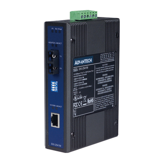
- Page 1 User Manual EKI-2541M/SC Ethernet to Multi-mode SC Type Fiber Optic Converter EKI-2541S/SC Ethernet to Single-mode SC Type Fiber Optic Converter...
- Page 2 No part of this manual may be reproduced, copied, translated, or transmitted in any form or by any means without the prior written permission of Advantech Co., Ltd. The information provided in this manual is intended to be accurate and reliable.
- Page 3 This product has passed the CE test for environmental specifications when shielded cables are used for external wiring. We recommend the use of shielded cables. This type of cable is available from Advantech. Please contact your local supplier for ordering information.
- Page 4 Safety Instructions Read these safety instructions carefully. Retain this user manual for future reference. Disconnect the equipment from all power outlets before cleaning. Use only a damp cloth for cleaning. Do not use liquid or spray detergents. For pluggable equipment, the power outlet socket must be located near the equipment and easily accessible.
-
Page 5: Table Of Contents
Contents Chapter Overview..........1 Overview ....................2 1.1.1 Fast Fiber Converters Module ............2 1.1.2 Dual Power Input ................2 1.1.3 Flexible Mounting................2 1.1.4 Advanced Protection..............2 1.1.5 Wide Operating Temperature ............2 1.1.6 Easy Troubleshooting ..............2 Features ....................3 Specification.................... - Page 6 EKI-2541(BE) User Manual...
-
Page 7: Chapter 1 Overview
Chapter Overview Sections include: Introduction Features Specifications Packing List Safety Precaution... -
Page 8: Overview
Overview The EKI-2541M/2541S is a cost-effective solution for the converting between 10/ 100Base-TX and 100Base-FX cabling, it allows you to extend the cabling distance of your 100Base-FX network up to 2 kilometers for multi-mode fiber or 30 kilometers for single-mode fiber. The Fast Fiber Converter module gives you the option to choose from the most popular fiber cabling connectors: SC multi-mode and single-mode con- nector. -
Page 9: Features
Features Provides 1 x 10/100Mbps Ethernet ports with RJ-45 connector Provides 1 x SC (multi-mode & single-mode) fiber connector Supports full/half duplex flow control Supports store & forward transmission supports auto-negotiation Supports MDI/MDI-X auto-crossover Provides surge protection (EFT) 3,000 V for power line ... -
Page 10: Specification
Specification Communications Compatibility IEEE 802.3, 802.3u, 802.3x 10/100Base-TX Multi-mode Fiber: Up to 2km Transmission Distance Single-mode Fiber: Up to 30km Transmission Speed Up to 100 Mbps Interface 1 x RJ-45 Connectors 1 x SC type fiber connector ... -
Page 11: Packing List
Packing List 1 x EKI-2541M or EKI-2541S Industrial Ethernet to Fiber Optic Converter 2 x Wall Mounting Bracket and Screws 1 x DIN-rail Mounting Bracket and Screws 1 x EKI-2541M/2541S Startup Manual Safety Precaution Caution! IF DC voltage is supplied by an external circuit, please use a protection device on the power supply input. - Page 12 EKI-2541(BE) User Manual...
-
Page 13: Chapter 2 Installation
Chapter Installation Sections include: LED Indicators Dimensions Mounting Network Power Connection... -
Page 14: Led Indicators
In this chapter, you will be given an overview of the EKI-2541M/2541S hardware installation procedures. LED Indicators There are few LEDs display the power status and network status located on the front panel of EKI-2541M/2541S, each of them has its own specific meaning as below table. -
Page 15: Dip-Switch
DIP-Switch The DIP-Switch is used to configure operation mode for LFP (Link Fault Pass- Through) and operation mode for UTP/Fiber port. The default value of DIP-switch is OFF. Table 2.2: Table 2.2: EKI-2541M/S DIP-Switch Definition S/W No Status Description Enables Port/Power Alarm Disable Port/Power Alarm Enables LFP Disables LFP... -
Page 16: Dimensions (Units: Mm)
Dimensions (units: mm) Figure 2.1 Front View of EKI-2541M/S EKI-2541(BE) User Manual... - Page 17 Figure 2.2 Side View of EKI-2541M/S EKI-2541(BE) User Manual...
- Page 18 Figure 2.3 Rear View of EKI-2541M/S EKI-2541(BE) User Manual...
- Page 19 Please refer to page 16 for pin assignment. Figure 2.4 Top View of EKI-2541M/S EKI-2541(BE) User Manual...
-
Page 20: Mounting
Mounting The EKI-2541M/2541S supports two mounting methods: DIN-rail & Wall. 2.4.1 Wall mounting EKI-2541M/2541S can be wall-mounted by using the included mounting kit. Then, hang on the EKI-2541M/2541S to the nails on the wall. First, use the screws included in the package to combine the EKI-2541M/2541S and metal mounting kit. -
Page 21: Din-Rail Mounting
2.4.2 DIN-rail Mounting You can also mount EKI-2541M/2541S on a standard DIN-rail by below steps. The DIN-rail kit is screwed on the industrial switch when out of factory. If the DIN-rail kit is not screwed on the industrial switch, please screw the DIN-rail kit on the switch first. -
Page 22: Network Connection
Network Connection Twisted-pair segment can use unshielded twisted pair (UTP) or shielded twisted pair (STP) cabling. The cable must comply with the IEEE 802.3u 100Base-TX standard for Category 5. The cable between the converter and the link partner (switch, hub, workstation, etc.) must be less than 100 meters (328 ft.) long. Fiber segment using single-mode connector type must use 9/125µm single- ... -
Page 23: Chapter 3 Troubleshooting
Chapter Troubleshooting... -
Page 24: Power Input
Power Input Verify that is using the right power cord/adapter (+12~48 V ), please don’t use the power adaptor with DC output voltage higher than 48V, or it will burn this converter down. Cable Select the proper UTP/Fiber cable to construct your network. The single-mode con- verter must use single-mode fiber cable. -
Page 25: Appendix A Pin Assignment & Wiring
Appendix Pin Assignment & Wiring... - Page 26 It is suggested to adopt ELA/TIA as the wiring of the RJ-45. Figure A.1 RJ-45 Pin Assignment Figure A.2 EIA/TIA-568B Figure A.3 EIA/TIA-568A EKI-2541(BE) User Manual...
- Page 27 EKI-2541(BE) User Manual...
- Page 28 No part of this publication may be reproduced in any form or by any means, such as electronically, by photocopying, recording, or otherwise, without prior written permission from the publisher. All brand and product names are trademarks or registered trademarks of their respective companies. © Advantech Co., Ltd. 2021...
Need help?
Do you have a question about the EKI-2541M/SC and is the answer not in the manual?
Questions and answers